|
© 2009 Guy Holt ------- All Rights Reserved ------- May not be reproduced without written permission.
|
Introduction
Given the wide variety of generators manufactured for different markets, it is important to understand the benefits and drawbacks to each when it comes to their use in
motion picture production. Especially, given that the increasing use of personal computers and microprocessor-controlled recording equipment in HD production has created
an unprecedented demand for clean, reliable power on set at a time when the trend in lighting is toward light sources that generate dirty power.
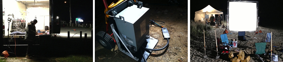
The power waveform below left is typical of what results
from the operation of a couple of 1200W HMIs with non-power factor corrected ballasts on a conventional portable generator. The adverse effects
of the harmonic distortion exhibited here, can take the form of overheating and failing equipment, efficiency losses, circuit breaker trips, excessive
current on the neutral wire, and instability of the generator voltage and frequency. Harmonic noise of this magnitude can also damage HD digital cinema
production equipment, create ground loops, and possibly create radio frequency (RF) interference.

Left: Distorted power waveform created by Non-PFC 1200W HMI ballasts on conventional generator.
Right: Near perfect power waveform created by the same lights as part of a new production system.
Why is harmonic distortion suddenly an issue in motion picture electrical distribution systems? First, one must appreciate that the power generation and electrical
distribution systems developed for motion picture production were never designed to deal with an abundance of non-linear loads like the electronic HMI and Fluorescent
lighting ballasts prevalent today. In the past, attention was given to portable generator features such as automatic voltage regulation and speed regulation. But, given the
increasing prevalence
of harmonic currents and the problems they cause, an increasingly more important feature today is the quality of the generated power waveform and how well it interacts
with today's light sources.
As production gets more electronically sophisticated, a thorough understanding of the demands placed on portable generators by such production equipment is necessary in
order to generate power that is clean and reliable. To generate power safely, it is important to understand the grounding requirements of the different types of portable generators.
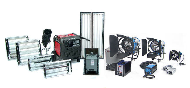
Our modified Honda EU6500is with our Transformer/Distro can power
the PFC 2.5 & 1.8 HMI Pars, PFC 400w
Lighthouse HMI,
2 ParaBeam 400, 2 ParaBeam 200s, and 2 Tegra 400s of our HD P&P Pkg.
It is the intent of this article to establish a foundation of knowledge that will enable us to build a new production
system that generates the clean stable set power (seen in the waveform above right) capable of operating larger lights (HMIs up to 6kw or Quartz lights up to 5kw),
or more smaller lights, off of portable gas generators than has ever been possible before. With this knowledge we will be able to also parallel two Honda EU6500 or EU7000
generators for an unprecedented 100A or 120A output from putt-putts.
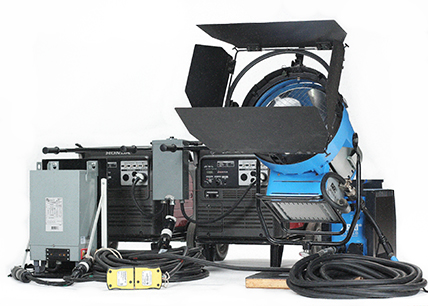
(Our new HD Plug-n-Play Paralleling System can power
the new 9kw Arri M90 HMI as
well as 4000W of additional lights)
To deliver this power safely under hazardous conditions, this knowledge will enable us to develop reliable ground fault protection systems using
film style GFCIs, like the Shock Stops, that are specifically designed for motion picture applications. But, before we can begin to build the edifice
of this new production system, we must first lay a foundation with the basics of power generation.

A film style Shock Stop GFCI can provide reliable ground fault protection on wet hazardous
filming locations
__________________________________________________________________
Table of Contents
(Click to jump to subject. Use "Back Button" to return to Table of Contents)
Generator Basics
Lighting Load Types
Harmonics
Interpreting the Sines
Inverter Generators
A Production System for a New Age
Conclusion
__________________________________________________________________
Generator Basics
An electric generator is a device or machine that is used to convert mechanical energy into electrical energy. It is based on the principle of electromagnetic
induction, a scientific law that was discovered by British scientist Michael Faraday and American scientist Joseph Henry in 1831. The principle states that when
an electric conductor, such as a copper wire, is moved through a magnetic field, electric current will flow through the conductor. The mechanical energy of the
moving wire is converted into the electric energy. Faraday and Henry also found that when you move a magnet in a coil of wire, electric current is generated.

A rudimentary electrical generator with static magnets and rotating current carrying coils
A generator produces an Electromotive Force (emf) by changing the number of Magnetic Flux Lines (Lines of Force), passing through a Wire Coil. In the rudimentary
electrical generator illustrated above and below, when the Coil is rotated between the Poles of the Magnet by cranking the handle, an AC Voltage Waveform is produced.

A generator operates on the principle of Electromagnetic Induction, which is defined by Faraday’s Law, which states:

Faraday's Law
The Electromotive Force, (emf) induced in a Coil is proportional to the number of turns, N, in the Coil and the Rate of Change of the number of Magnetic Flux Line passing through the surface (A) enclosed by the Coil. In the rudimentary generator illustrated here, the Coil is under a Stationary Magnetic Field. The Magnetic Flux Density, B, is constant and so Lines of Force is proportional to the Effective Area, Aeff, of the Loop (Lines of Force = B x Aeff.) As the Loop rotates at different angles, there is a change in Aeff which is shown in the illustration below.

Effective Area of the Wire Loop at Different Rotational Angle
The Rate of Change of the Lines of Force is the largest at the zero points of the Waveform and is the smallest at the peaks of the Waveform. Since, an Induced
Effect is always opposed to the cause that produced it, the Induced emf is maximum at the zero points and minimum at the peaks as illustrated below. To see why that is, let’s look more closely at what happens as the loop rotates.

Different Rates of Change of the Magnetic Flux
at Various Rotational Angles
In the loop diagrams below, the loop is rotating in a clockwise direction. At position A, the top leg (black) is moving toward the south pole, and the lower leg (white) toward the north pole. In position A, no flux lines are being cut since both legs are moving parallel to the lines of flux. Since no flux is cut, no voltage is induced. In position B, the loop has rotated 1/4 of a turn (90°). The black leg is now moving downward, and the white leg is moving upward. In this position, both legs are cutting across a maximum number of lines of flux, and the emf is maximum. At position C the loop has rotated 1/2 of a turn. The two legs are once more moving parallel to the lines of flux, and again no voltage is induced. At position D, the black leg is moving upward, and white leg downward. Both legs are again cutting a maximum number of lines of force, but in the direction opposite to that of position B. Since the legs are cutting the field in the opposite direction, the emf induced causes the current to flow in the opposite direction. The next 1/4 turn brings the loop back to position A, and the cycle starts over again.

Position of the Rotating Wire Coil Plane to the Magnetic Field Direction
and the Induced Electromotive Force
If we were to plot on a graph this induced emf against coil rotation, we would get the sinusoidal waveform that appears below the loop diagrams in the illustration above.
Line X-X' is the zero line. All the area above this line is positive (+), and the area below is negative (-). A careful plotting of induced emf through one rotation of the
coil reveals that a sinusoidal voltage waveform is the natural result of the mechanical motion of a generator’s coils. For example, in position A on the illustration of the
coil rotation, the loop is cutting no lines of force so the induced emf is zero (point 1 on the graph.) One quarter turn later, the loop is in position B. It is cutting a
maximum number of lines of force, so the emf is maximum (point 2 on the graph). At position C, the loop has completed 1/2 of a turn, and no lines of flux are being cut, so
the emf is back to zero at point 3 on the graph. In position D, the loop is cutting the field in the direction opposite to that of position B. The emf induced in the coil i
s maximum, but in the opposite direction (point 4 on the graph). Position E is the same as A, so the loop is ready to start over again. If we were to summarize what happens
during one full rotation of the coil: it starts at zero, rises to maximum in one direction (+), falls back to zero, rises to maximum in the opposite direction (-), and then
comes back to zero. Since, an alternating emf causes the current to flow first in one direction and then the other it is called, Alternating Current, or just plain A.C.. A complete rotation is called a Cycle. If the generator coil is made to turn 60 complete rotations in one second, the Frequency of rotation is 60 Cycles per second. If we plot
induced emf against coil rotation at 60 Cycles per second we get the familiar AC voltage sine wave - the Alternating Current (AC) used in commercial electrical power systems.
Generator Anatomy
In order to obtain a larger emf, some generators use stronger rotating electromagnets instead of the fixed permanent magnet of our illustration. An electromagnet consists of a coil of wire which
acts as a magnet when an electric current passes through it, but stops being a magnet when the current stops. The electromagnets are mounted on a shaft (called the Rotor) and rotated within electrical
coils (called the Stator.) Illustrated below is the anatomy of a Honda conventional generator. It consists of a stationary Stator and a two pole Rotor that spins inside the Stator.

When the Rotor is rotated, electrical current is induced in the Armature coils of the Stator. The Armature is connected directly to the
electrical outlets. Each time the Rotor makes one complete revolution, one complete cycle of AC is generated. And, since the Rotor rotation produces different directions to the +/- poles of the magnetic field at different points in
time, the voltage generated is sinusoidal (AC), and each full engine rotation produces one complete AC sine wave. Consequently, the engine must spin the generator
Rotor 3600 RPM to produce the 60Hz AC frequency required in North America (60 cycles/second x 60 seconds/minute = 3600RPM). If, because of varying loads, the
Rotor spins faster or slower, the voltage and frequency of the output vary in step. Since generators must operate at a constant speed in order to maintain a constant AC Frequency (Hz), the voltage of the AC output is therefore
a function of the level of the excitation of the Rotor’s electromagnets. The quality of the electricity a conventional generator puts out then
is determined by the quality of the engine, how smoothly it runs, and how well the engine is capable of maintaining a constant speed.
The Stator assembly consists of insulated windings (Armature coils) positioned near an air gap in the Stator core in which the Rotor rotates. The number and the way the
Armature coils are connected determine the phase of the power generated. The Stator of a single phase generator, like the Honda EX5500 illustrated above, has two
sets of Armature coils which are spaced 180 degrees apart (a three phase generator has three sets of coils spaced 120 degrees apart.) As illustrated in the wiring schematic below, one end of each coil is
connected to a common neutral terminal. The other end of each coil is connected to separate terminals. Conductors attached to the three terminals (hot, hot,
neutral) carry the current to the generator’s distribution panel (load bus) and on to the electrical load.

Generator Wiring Schematic
As such a single phase generator, like the EX5500, has two separate main power producing circuits. These two circuits supply equal power to the receptacles shown below when the voltage selector switch is in the "120/240V" position. With single phase generators, when the distribution panel has two or more receptacles, you must balance the total load on the generator by dividing the individual loads between the two main power circuits.

For example, the Honda EX5500 is rated for a continuous load of 5000W (41.7A total or 20.8A/main circuit). Now, if receptacle 2 (R2) in the illustration above has a 2k light (a 16.8A load) connected to it and receptacle 3 (R3) has a 1k light (a 8.4A load) connected to it, the total power draw on Main Circuit 1 is 25.2A (greater than the 20.8A capacity of Main Circuit 1). This is a substantial overload to this circuit. Main Circuit 1 is substantially overloaded because both receptacles (R2 & R3) are powered by Main Circuit 1. To eliminate the excessive power draw on Main Circuit 1, the load from receptacle 3 (R3) should be switched to receptacle 1 (R1). Now Main Circuit 1 is powering a 16.8A load (less than 20.8A) and Main Circuit 2 is powering a 8.4A load (less than 20.8A).

ILLUSTRATION COURTESY OF HONDA POWER PRODUCTS
In small portable gas generators the generator end (called the alternator) is direct-coupled to the engine to provide smooth operation. Alternator housings are bolted directly to the engine providing precise rotor and
stator alignment.
__________________________________________________________________
Portable Generator Types
What differentiates generators is how they go about regulating the voltage and frequency (Hz) of the AC power they generate through magnetic induction. A generator that is intended to power only the universal motors found in power tools and the incandescent lights found on construction sites requires very little power regulation because their intended loads are very forgiving. Where as, a generator that is intended to power sophisticated electronic equipment that is voltage and frequency sensitive, requires sophisticated and costly power regulation. Where there is a direct trade-off between cost and power quality, the degree to which a generator regulates its power depends upon the requirements of the loads it is intended to power.
For example, since it is less expensive to make a relatively simple generator that will satisfactorily operate most construction equipment and RV appliances (but not sophisticated electronics), there is not the cost/benefit return to warrant the incorporation of the more expensive power regulation controls in generators manufactured for these markets. This explains why there are basically four types of generators available on the market to this day. Given this variety of generators manufactured for different markets, it is important to understand the benefits and drawbacks to each when it comes to their use in motion picture production.
Where what differentiates one type of generator from another is the quality of its’ power it is important to understand the AC power waveform. AC Power is depicted using a sine wave.
The sine wave is a way for us to graphically represent how electricity works. The sine wave is measured using an oscilloscope. The vertical axis represents amplitude (this may be represented in Volts.) The horizontal axis (degrees) represents time and is also known as wavelength. Notice how the voltage sine wave above starts at 0. It then reaches its peak at 90º. This is where the voltage is at its positive maximum. The wave then crosses 0 volts again at 180º (this is called the zero crossover) before peaking again at 270º in the negative and returning to 0 volts at 360º. This process is called a cycle. The frequency of cycles per minute is measured in Hz (Hertz). The standard in North America is 60Hz.

Pure Sinusoidal Power Waveform
A pure sinusoidal voltage, like the one represented above, is a conceptual quantity produced by an ideal AC generator built with finely distributed stator and field windings that operate in a uniform magnetic field. Since in reality neither the winding distribution nor the magnetic field can be uniform in a working AC generator, voltage waveform distortions are created, and the voltage-time relationship deviates from our conceptual pure sine function. The smoother the curve of the sine wave, the more stable the power. Any spikes or "blips" in the curve are caused by a fluctuation in the power. These can be bad for both your generator and the equipment being powered.
Here are the representative waveforms, and brief descriptions, of the four types of generators available on the market today. Given the importance of understanding the benefits and drawbacks to each when it comes to their use in motion picture production we will examine each type of generators, as well as the typical loads they will power on a set, in more detail latter.
 |
Brushless Generators: Among the most common because of their inexpensive construction, brushless generators have the least reliable voltage control. Brushless generators can't react
quickly to changing loads, either producing low power (a brownout) or high power. Fluctuations of this nature will cause voltage sensitive equipment like HMI lights
to shut off, or will damage sensitive electronics. With a substantual voltage waveform distortion of 23%, brushless generators do not interact well with HMI and Kino Flo ballasts. For this reason brushless generators are only suitable for powering incandescent lighting.
|
 |
AVR Generators (Digital or Analogue):
AVR generators feature either a digital or analogue Automatic Voltage Regulator designed to control voltage. Whether digital or analogue the AVR attempts to keep the output voltage more or less constant,
regardless of the load. With no large fluctuations in voltage resulting from changing loads, AVR generators will, for the most part operate HMI lights
reliably. With older magnetic HMI ballasts, AVR generators require frequency governors to eliminate flicker on film and scrolling in video. With an
appreciable voltage waveform distortion of 19.5%, AVR generators do not interact well with non-power factor corrected HMI and Kino Flo ballasts.
|
 |
MSW Inverter Generators:
“CycloConverter”, “Modified Sine Wave”, “Psuedo Sine Wave” are different manufacturer’s trade names for modified square wave inverter generators. These generators
use inverters to produce not a sine wave, but a modified square wave that, depending on their cost, more or less resembles a sine wave. Where the modified square wave is generated from
switching DC power that is converted from the AC power the alternator generates, the power MSW Inverter generators generate is cleaner and more stable than
AVR generators. With a slight voltage waveform distortion, MSW Inverter Generators will interact reasonably well with HMI and Kino Flo ballasts. However,
a modified square wave will cause sensitive electronic equipment (computers, hard drives, video cameras) to overheat. While, equipment that depends on peak
voltage (battery chargers) will not operate as effectively on a modified square wave. For these reasons MSW Inverter Generators are less than ideal for HD
digital cinema productions.
|
 |
PWM Inverter Generators:
PWM Inverter Generators operate like MSW Inverter Generators, but use a sophisticated pulse width modulation (PWM) logic to control a micro processor to switch IGBTs at high
speeds to produce a near pure sine wave from the DC power that is converted from the AC power of the generator alternator. With a negligible voltage waveform distortion of 2.5%
(less than grid power), PWM Inverter Generators interact well with HMI and Kino Flo ballasts. These units are ideal for sensitive electronics, such as computers, audio, and
video recording equipment. PWM Inverter Generators offer a number of other benefits, including less noise, lower weight, and greater fuel efficiency as compared to conventional
AVR Generators.
|
WAVEFORMS COURTESY OF HONDA POWER EQUIPMENT
__________________________________________________________________
Voltage Regulation
A conventional generator rotates two magnets inside its Stator core. Since the rotation produces different directions to the +/- poles of the magnetic field at different points in its circular
motion, the voltage generated is sinusoidal, and each full engine rotation produces one complete sine wave. By design, the engine must spin the generator rotor 3600 RPM to produce an AC
frequency of 60 Hz (60 cycles/second x 60 seconds/minute = 3600RPM). If, because of varying loads, the generator spins faster or slower, the voltage and frequency of the output vary in step. The
quality of the electricity a conventional generator puts out then is determined by the quality of the engine, how smoothly it runs, and how well the engine is capable of maintaining a constant
speed. Which makes a generator’s ability to recover engine speed after the application of a transient load a key requirement to maintaining uniform power output. Besides being affected by loading
and transients, other factors, such as cold-to-hot drift, frequency effect, and ambient temperature changes, also affect the voltage output of conventional generators. Voltage regulation must
therefore encompass all of these variables in order to keep a generator’s voltage output within a given percentage of a specified value.
Brushless Generators
Among the most common because of their inexpensive construction, brushless generators have the least reliable voltage output of all generators. Without brushes or slip rings to conduct Exciter
Current to the Rotor, brushless generators rely on the inherent magnetic strength of the Rotor magnets to create field flux. Absent a variable Exciter Current, this approach to voltage regulation
is called “Constant Regulation.”

The North Star Brushless Generator
With constant voltage regulation, additional load causes the terminal voltage of the generator to decrease to a lower value until it reaches a state of equilibrium. This lower voltage depends upon the inherent field strength of the Rotor and the size of the load. For most motion picture lighting applications, Constant Regulation is inadequate and can even lead to the engine not being able to recover speed after adding load.
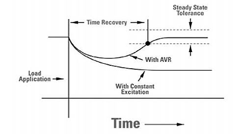
Voltage Drop with constant excitation of Constant Regulation
verses the variable excitation of AVR systems
Voltage Drop of the nature illustrated above can result in the following scenario we have all probably experienced at one time or another when trying to run multiple HMI lights with magnetic
ballasts on industrial brushless generators. After turning on the first HMI light, you switch on a second light. The sudden load of the striking second HMI ballast creates a sudden surge in
the power load, which causes momentary engine instability and a dip in output voltage. The dip in voltage causes both HMI lamps (the one already running and the one striking) to cut out. Since
the metals in the striking HMI lamp did not reach a full gaseous state before the light cut out, they fuse to the quartz envelope rather than being re-deposited in metallic form, thereby
appreciably shortening the life of the globe. As this scenario demonstrates, the voltage drop under load of brushless generators make them only suitable for powering incandescent lights and not much else.
Another problem with brushless generators is that the power they generate exhibits significant voltage waveform distortion (see waveform above). With an applied voltage waveform distortion of upwards of 23%, brushless generators do not interact well with HMI and Kino Flo ballasts, causing harmonic currents to be thrown back into the power stream, which results in a further degradation of the voltage waveform (more on that latter.)
AVR Generators
To maintain voltage output within tighter limits, better portable generators use an Automatic Voltage Regulator (AVR.) Generator AVRs vary widely in design, but on the most fundamental level, an
AVR regulates voltage output by first sensing the voltage level generated in separate Sensing Coils in the Stator and then comparing it to a reference. The reference is often a zener diode, which
is a very stable voltage device. A desired voltage level is then set by the operator using a voltage adjustment rheostat. The AVR than compares the set value to the sensor voltage and generates
an “Excitation Current” to increase or decrease the field strength in electromagnets (rather than a permanent magnet) in the Rotor.

Rotor Electromagnet Excitation Circuit
The excitation circuit (illustrated above), consists of slip rings and brushes attached to the engine shaft (not illustrated.) DC power is used to excite the electromagnets of the Rotor and
flows from the exciter (AVR), through the negative brush and slip ring, to the Rotor field poles to establish the magnetic fields. The return path to the Exciter is through the positive brush
and slip ring.
The amount of excitation required to maintain the generator output voltage constant is dependant on the load on the generator. If the output voltage from the stationary Stator coils dips due to
engine fluctuation from an increase in demand (this is called a Transient Dip), more current is fed by the AVR into the rotating electromagnets through the Excitation Circuit. This increases the magnetic field around
the Rotor electromagnets, which induces a greater voltage in the main Stator coils. Thus, the output voltage is brought back up.
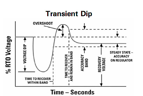
AVRs are not full proof because they are generally slow to respond to transient loads. For instance, by the time the AVR senses and responds to the need to drop the excitation once more, the voltage may tend to overshoot (see illustration above.)
As a consequence of constant adjustments in a
power feedback loop consisting of the Sensor Coils, AVR (Exciter), and Rotor electromagnets, voltage oscillation occurs in increasingly smaller oscillations until it finally stabilizes.
The degree to which an AVR permits voltage output to oscillate is an important consideration when choosing a portable generator for motion picture lighting applications. Too large an overshoot
could potentially cause a short circuit in sensitive electronic equipment operating on the power. Too large a transient dip could potentially cause the main generator voltage to collapse or
“fold-up.” How? Remember, the excitation voltage for the Rotor magnetic field of a brushless generator is provided by the generator output. For steady-state loads and most transient loads,
this power is sufficient. But, under severe sudden loading, like that of a striking magnetic HMI ballast, the generator output voltage can drop to a point where the AVR does not have sufficient
power to operate - resulting in a reduction in voltage to the exciter field, when a boost is required, and so the generator is not able to recover from the sudden load.
Fluctuations of this nature can result in the following scenario when trying to run multiple HMI lights with conventional AVR generators. After turning on the first HMI light, you switch on a second light. The striking of the second HMI ballast creates a surge in the power load, which causes momentary engine instability and a dip in output voltage. The dip in voltage causes both HMI lamps (the one already running and the one striking) to cut out. When, within seconds, the engine stabilizes again, the power comes back up to full or even more, which causes the HMI light that cut out to hot re-strike (because the ignition switch is still on.) But, because the lamp is hot, the strike doesn’t take. The striking voltage returns to the ballast and fries delicate electrical components in the ballast. For this reason the speed at which an AVR responds to transient loads is an important consideration when choosing a portable generator for motion picture lighting applications.
Fast vs Slow AVRs
The ability of an AVR to recover terminal voltage to its initial value or a value within the steady-state tolerance depends on its response time.
The illustration below shows the results of faster and slower response times of excitation and regulation systems to transient load.

As illustrated above, the voltage dip is greater for the slow response system than for the fast response system. And, since the voltage drop continues to follow the inherent regulation characteristic curve for a longer period of time, by the time the AVR does act, the recovered steady-state value is lower than the faster system voltage. Without a doubt, the quicker an AVR can respond to changes in load, and with a higher excitation current, the more likely terminal voltage will recover its initial value or a value within an acceptable steady-state tolerance for motion picture lighting instruments.
Now a days, high end conventional (as opposed to inverter) portable generators come in two distinct varities: those with Digital AVRs and those with Analogue AVRs. Regardless of the type of AVR, to be suitable for filming with all types of HMI ballasts
conventional generators must also employ a governor
system to maintain near constant AC Frequency ( +/- .25 cycles of 60 Hz (i.e.59.75 - 60.25 Hz.)) Before we look at the two types of AVR systems, lets first look at how and why AC Frequency is regulated in generators.
AC Frequency Governors
To be suitable for lighting with all HMI ballasts, as well as sophisticated electronic production equipment like laptops, hard drives, and HD monitors, conventional generators require a AC Frequency governor. Broadly speaking, HMI ballasts now come in two
varieties. They are magnetic ballasts and electronic square wave ballasts, also called flicker free ballasts. For the purpose of this discussion, I will not refer to electronic square wave ballasts as flicker free, because that implies that magnetic
ballasts generate flicker, which they do not under controlled circumstances. To avoid “flicker” with magnetic HMI ballasts operating on conventional generators, the generator speed must be tightly governed to within +/- .25 cycle of 60 Hz (i.e. 59.75 - 60.25 Hz.) The need for such tight control of the AC
frequency has to do with the fact that HMI lights are inherently arc lights whose output pulsates.
If you were to look at an HMI globe, instead of a coiled tungsten filament glowing, you would find an electrical arc spanning the gap between two opposing electrodes. On the most fundamental level, a magnetic HMI ballast is simply a variable transformer choke between the power supply and the lamp electrodes. The transformer provides the start-up charge for the igniter circuit, rapidly increasing the potential between the electrodes of the head’s arc gap until an electrical arc jumps the gap and ignites an electrical arc between the lamp electrodes. The transformer then shifts gear and acts as a choke, regulating current to the lamp to maintain the pulsating arc once the light is burning.
As such, the light intensity of a HMI powered by a magnetic ballast follows the waveform of the supply power and increases and decreases 120 times a second, twice every AC cycle. This fluctuation in the light output is not visible to the eye but will be
captured on film or video if the frequency (Hz) of the AC power is not precisely synchronized with the film frame rate or video scan rate. If the AC Frequency of the power were to vary appreciably, a frame of film or video scan would receive more or less exposure
depending upon the exact correspondence of the film/video exposure interval to the cycling power waveform because the light intensity is pulsating at twice the AC frequency.

ILLUSTRATION COURTESY OF HARRY BOX
The normal sinusoidal 60Hz current of a magnetic ballast (left) creates a fluctuating light output (right)
requiring that the camera frame rate be synchronized with the light fluctuations to obtain even exposure frame to frame.
In film production with magnetic HMI ballasts (as opposed to video), to avoid this flicker you must also use a crystal controlled camera, run the camera at one of a number of safe frame rates (those that can be divided into 120 and result in a whole number),
and use power that is regulated to within a quarter cycle of 60 Hz (59.75 Hz - 60.25 Hz.)

The problem one encounters when operating magnetic HMI ballasts on conventional generators is that by design the AC frequency they generate is a function of engine speed and their speed fluctuates. As the generator spins faster or slower, the frequency of the output varies in step. For this reason, when filming with magnetic HMI ballasts, a separate governor is required to ensure that the engine spins its’ core at a near constant 3600 RPM to produce the desired AC Frequency of 60 Hz (60 cycles/second x 60 seconds/minute = 3600RPM).

A Barber Coleman AC Frequency Governor in a Honda EX5500
An AC Frequency governor accomplishes this by first monitoring the engine speed, it then compares that reference signal with an internal quartz crystal reference, and corrects any error by adjusting the engine throttle through a mechanical linkage (see picture above.) By constantly adjusting the engine speed in this fashion the governor ensures a more or less stable 60 Hz AC Frequency. It is worth noting here, for the purpose of our latter discussion regarding the adverse effects of power waveform distortion, how the governor system obtains its’ engine speed reference.
Larger generators that are designed to take AC frequency governors, have a magnetic pick up that senses the rotation of the core. However, since the AC frequency governors for portable gas generators are after market modifications, the engine speed reference signal is obtained by measuring the frequency of the output voltage inside the AVR unit. By sensing the zero-crossing information from the waveform, the AC frequency governor can precisely regulate the engine speed and in theory eliminate erratic exposure of film frames or video scans.
In practice, AC governor systems work well in small portable generators only if the generator is well maintained, finely tuned, and carefully prepped for each shoot. The carburetors of small generator engines are easily gummed up by old fuel making them run rough. For this reason, it is important to bleed old fuel from the system and replace it if the generator as been sitting idle for an extended period of time. A second maintenance issue is that the generator battery must be at full capacity as well as fully charged. The reason for this requirement is that the battery charging system of the generator was not designed for the additional electrical load of the AC Frequency governor. If the generator battery is not at full capacity and fully charged, the AC Frequency governor eventually runs the battery down to the point that it can no longer regulate the engine because it is underpowered. Unfortunately, more often than not, the generators coming out of rental houses are poorly maintained and inadequately prepped making the AC governor system ultimately unreliable.

ILLUSTRATION COURTESY OF HARRY BOX
The refined square-wave signal of an electronic ballast (left) creates virtually even light output (right)
When electronic square wave HMI ballasts came on the market, they were at first thought to be the solution to all the problems inherent in running HMI lights on small portable generators. By eliminating the flicker problem associated with magnetic ballasts, they also eliminated the need for the expensive and ultimately unreliable AC governors required for flicker free filming with magnetic HMI ballasts and portable gas generators. Electronic square wave ballasts eliminate the potential for flicker by squaring off the curves of the AC sine wave supplying the globe. Squared off, the changeover period between cycles is so brief that the light no longer pulsates but is virtually continuous. Even if the AC Frequency of the power were to vary, a frame of film or video scan, would receive the same exposure because the light intensity is now not pulsating but nearly constant. Electronic square wave HMI ballasts allow you to film at any frame rate and even at a changing frame rate.
Since they are not frequency dependent, it was thought at first that electronic square wave ballasts would operate more reliably on small portable generators – even those without frequency governors. For this reason, as soon as electronic square wave ballasts appeared on the market, many lighting rental houses replaced the more expensive crystal governed portable generators with less expensive non-synchronous portable generators. The theory was that an electronic square wave ballast would operate reliably on a non governed generator and allow filming at any frame rate, where as a magnetic HMI ballast operating unreliably on a AC governed generator allowed filming only at permitted frame rates.
In practice, electronic square wave ballasts turned out to be a mixed blessing. Part of the problem with operating electronic HMI ballasts on portable gas generators in the past has to do with the purity
of the power waveform they generate. With an applied voltage waveform distortion of upwards of 19.5% and a high internal reactance, conventional AVR generators do not interact well with electronic HMI
ballasts, causing the harmonic currents they throw back into the power stream to distort the voltage waveform which ultimately can lead to equipment failure or damage (more on that latter.)
Digital vs. Analogue AVR Systems
To avoid the nightmare scenarios described above when striking multiple HMIs, a portable generator must have an Automatic Voltage Regulator (AVR) capable of restoring voltage output to within ±3% of the mean voltage after even very heavy transient loads. To review, whether Digital or Analogue, an AVR keeps the output voltage more or less constant,
regardless of the load. It accomplishes this by first monitoring the output voltage. It then compares it with the desired set value and corrects any discrepancy by suitably changing the field excitation current. By constantly adjusting the excitation to the Rotor electromagnets to increase or
decrease the field strength in the Stator coils and hence the output voltage, the AVR ensures a more or less consistent flow of power regardless of the load. In this fashion, AVR systems eliminate surges and brown-outs that would otherwise occur when switching
on and off your lights (both HMI & Quartz.)
Analogue AVR Systems

The Honda EM6500 AVR Generator
AVRs have evolved from the early electromechanical types to solid state AVRs that use closed loop analogue circuits to control the field excitation in the generator’s Rotor electromagnets. Under normal circumstances, a run of the mill analogue AVR system can ensure a
voltage that
is within ±5% of the mean voltage. Unfortunately, given the size of portable generators (usually less than 7000W) relative to common motion picture lighting loads (upwards of 2000W),
analogue AVR systems of this type are not always responsive enough to sufficiently maintain voltage when switching on large motion picture lights.
Where the load placed upon the generator by a 1200W HMI (which draws anywhere from 13.5-19 Amps depending on the type of ballast), or a 2000W Quartz
light (which draws 16.8 Amps) can account for 30-60 percent of the capacity of the generator, an analogue AVR system is likely to be overwhelmed unless it is capable of ensuring a voltage that is within ±3% of the mean voltage. For this reason (and others),
the general rule of thumb when using conventional generators with analogue AVR systems is to oversize the generator by a factor of 2 to 1 relative to your total load. It also helps to use more small lights than just a few large lights.

Analogue AVR generators can have waveform distortion of upwards of 19.5%
Another drawback to Analoque AVRs is that the AC power waveform they generate has appreciable distortion. With waveform distortion of upwards of 19.5% (see detail of power waveform above right),
Analogure AVR generators do not interact well with non-Power Factor corrected HMI and Kino Flo ballasts (use this link for details.) .
Digital AVR (DAVR) Systems
Recent advances in microprocessor technology now make faster and more powerful AVRS available. Manufacturers of large diesel gen-sets are taking advantage of now relatively inexpensive microprocessor technology to implement more complex forms of
adaptive and fixed parameter based controllers in their generators. With the introduction of a digital AVR (DAVR) system into the company's all-new 10kw EB10000 generator, Honda is the first to integrate digital processing into the controller of a small
portable gas generator. Able to hold the voltage stable within ±1% of the mean voltage (as opposed to the ±3% of the best analogue AVRs), the EB10000’s DAVR substantially improves the output capability of the new model. What makes the output of Honda’s EB10000
more stable is that its’ DVAR is much more responsive than traditional analogue AVRs.

A 10kw Honda EB10000 with a Full Power Transformer/Distro
that provides a single 84A/120V circuit.
As we saw earlier, traditional AVRs use a closed feed back loop to stabilize voltage. As such, it takes comparatively longer to feedback and correct deviations from mean voltage caused by a sudden increase in load. Slower to
respond, analogue AVRs allow for larger fluctuations of voltage (±5%), which, for example, can cause an HMI to cut out if the voltage drops too low. Rather than use a closed feed back loop to stabilize voltage, a DAVR uses
control software with micro-second sampling rates of the output power of the main Stator windings (as compared to a sensor winding in conventional AVR systems) to more quickly and accurately detect deviations from the mean and make the necessary
adjustment to the excitation current in the Rotor electromagnets more rapidly. And, by directly sampling the main Stator windings, rather than a sensor winding, the DAVR obtains a more reliable indication of the output voltage -
the same one your loads see. The drawback to using a separate sensor coil is that the AVR does not see how voltage at the generator bus has been affected by changes in temperature, load current, and load harmonics. By applying
true RMS calculations to the actual voltage coming off the Stator coils, as opposed to an isolated sensor coil, the DAVR of the EB10000 has a more accurate reading of the bus voltage and so is able to make more accurate corrections
(see below for details.) But, in order to operate effectively, the power source for the DAVR has to be independent of the main Stator coils. For this reason,
the EB10000 is outfitted with indpendent power coils located below the engine flywheel. Here's why:

Honda EB10000 with Voltage Select 84A Transformer/Distro
and 14 Gallon Fuel Caddy
In a conventional AVR generator, as you may recall, there is a power feedback loop from the generator output (via the Sensor Coil) back through the Exciter (Automatic Voltage Regulator) to the electromagnets in the Rotor.
When the generator is subjected to a sudden heavy load (the strike of an HMI lamp for instance), there is a momentary "brown out" and the voltage to the AVR drops. Starved for power, the AVR is momentarily unable to
take corrective action and so the voltage dips further before power is restored to the AVR and it is able to correct the power output to full line level.
For this reason, the EB10000 uses what is called an IE excitation system (Independent Excitation) that consists of two special sets of coils that are wound to fit in carefully selected slots of
the main Stator. The special wire selected for the IE coils provide total separation and isolation from the Stator main winding. These two auxiliary windings are designed to provide constant
power to the EB10000’s DAVR. The two coils are connected in series to the input of the DAVR. One auxiliary winding produces a voltage proportional to the output voltage of the unit. The other
acts like a current transformer and produces a voltage proportional to the output current of the unit. The two windings combine to provide the DVAR with a constant voltage source that is unaffected
by transient loads. By drawing its' power from separate power coils, the voltage to the DAVR of the EB10000 is unaffected by momentary brown outs caused by sudden increases in load.
Independent of
the generator output, and consequently of sudden heavy loads, the EB10000's DAVR is able to respond more quickly to deviations from mean voltage. The result is that the generator is much better able to sustain output
current against transient loads and, therefore, it has a much lower internal reactance compared to conventional AVR machines. Able to respond more quickly to more accurate information, a DAVR is more able to maintain voltage
on a straight and narrow path (±1% compared to the ±3% of analoque AVRs.)

Honda’s intelligent computer-controlled iGX Series 630 688cc engine
Microprocessor control requires a new generation of smart engines. For this reason, the Honda EB10000 is equipped with Honda’s innovative iGX Series 630 688cc engine. One of Honda’s new generation of
intelligent computer-controlled engines, the GX630 features an integrated electronic control unit (ECU) that communicates with a self tuning regulator (STR) governor system. This allows the engine to
communicate with the microprocessor of the machine (generator) it is powering.

The control panel of the DAVR Honda EB10000
As the engine becomes intelligent, more of its’ operation can be automated. In addition to voltage regulation, the microprocessors of DAVRs make it possible to implement more complex forms of control
than were possible with analogue AVRs. Able to monitor many parameters almost
at once, Honda’s DAVR is able to run continuous self-diagnosis to quickly identify and prevent spikes in voltage and engine speeds for instance and communicate the results on its' "i-Monitor." In addition to the Under Voltage Monitoring (UVM) and Under
Excitation Monitoring (UEM) required for voltage regulation, DAVRs are able to also monitor and perform the following functions that a traditional AVR simply cannot:

The i-Monitor of the Honda EB10000 communicates the results of the DAVR's continuous self-diagnosis
Over Voltage Monitor (OVM):
An over-voltage function monitors the regulator sensed voltage and causes the regulator to shutdown when this sensed voltage exceeds a preset trip level (usually 115%) for a prescribed time (usually 0.75 seconds) .
Over Flux Monitor (OFM):
An Over Flux Monitor (field current limit function) monitors regulator output current and limits this current should a heavy load or short circuit occur across the field output terminals.
Over Excitation Monitor (OEM):
An over excitation function monitors the regulator output voltage and causes the regulator to shutdown when the output voltage exceeds a preset trip level for a prescribed time (usually 15 seconds.)
Over-Temperature Protection: (OTP):
The regulator is equipped with a sensor that monitors the ambient temperature and will turn itself off when the temperature exceeds 70° C.
Power Factor Monitoring (PFM): by measuring the "Root Mean Square" (RMS) of the voltage coming off the Stator coils, the DAVR of the EB10000 has a more accurate
reading of voltage waveforms that have been distorted by harmonic currents. By comparison, the “average reading, calibrated rms” measurements of conventional AVRs can be almost
40% lower than the real value (see below for details.)
With microsecond sampling rates, DAVRs are able to monitor all these parameters almost simultaneously and make nearly instantaneous adjustments. For example, at the start of a control routine, signal
inputs like line voltage and field current are read and excitation current adjusted every 10 msecs, resulting in the smoother Voltage waveform, with lower inherent distortion, seen in the oscilloscope shot below.

A DAVR's capability to make nearly instantaneous adjustments results
in a smoother AC waveform with lower inherent distortion
Operations, like the Over Excitation Monitoring and Over Flux Monitoring, that do not need to be cycled that quickly are done less frequently, but still within microseconds (typically 20- to 40 msecs.)
Even operations that require long calculations are only split over one or more cycles or done asynchronously in the background. Depending on the level of sophistication of the DVAR, such operations can
include Power Factor measurement, VAR control, event recording, data logging, and temperature calculations. In this fashion, DAVRs are able to provide a level of control far superior to that of analogue AVRs.

Left: Detail of AC Power Waveform generated by Digital AVR.
Right: Detail of AC Power Waveform generated by Analogue AVR.
An important benefit to filmmakers in using DAVRs is that the harmonic currents thrown back into the power system by the non-Power Factor corrected power supplies of HMI, Fluorescent, & LED lights will not
cause as severe Voltage waveform distortion as it does in Analogue AVR generators. As we will explore in more detail below, the lower the internal reactance of a generator to an instantaneous change
in load and the better the inherent waveform, the less harmonic currents will distort its' Voltage. Given its' tighter control, a DAVR is much better able to sustain output voltage against transient loads and, therefore,
it has a much lower internal reactance compared to conventional AVR machines. As is readily apparent in the waveforms distorted by the harmonics kicked back by a non-Power Factor corrected 1200W
electronic HMI ballast below, the cleaner power generated by a DAVR is appreciably less distorted (left) than the dirty power of an Analogue AVR (right.) Consequently, a DAVR generator will be able to reliably operate
a larger load than a comparatively sized Analogue AVR generator (see below for details.)

Left: Voltage Waveform Distortion from Non-PFC 1200W HMI Ballast on DAVR.
Right: Voltage Waveform Distortion from Non-PFC 1200W HMI Ballast on Analogue AVR.
The one power function that DAVRs are not able to control is AC Frequency (Hz) because it has to do with engine speed and not field excitation. For that reason, you should use only “flicker free” electronic
HMI ballasts on them. And, while markedly better than Analogue AVRs at handling harmonic currents, the Voltage waveforms generated by DAVRs are effected non-the-less and so only Power Factor Corrected (PFC)
HMI, Kino, and LED ballasts should be used on them.
But, when it comes to raw power, the EB 10000 is unparalleled. Used with our new 84A Full Power Transformer/Distro with “Voltage Select”, the EB10000 is capable of providing a silent 84 Amps, in a single 120V circuit, on set – enabling you to use larger lights (like
Nine-Light Maxi Brutes), or more smaller lights, than has ever been possible on a portable generator (use this link for details .)
How to Record Clean Audio Tracks with Industrial Generators
Some filmmakers hesitate to use open frame industrial generators like the new 10kw Honda EB100000 because of the noise they make - don't. Whether you pick up generator noise on your audio
tracks comes down to how you use it. Our HD Plug-n-Play system is specifically designed to enable you to record clean audio with the Honda EB10000 even under the worse case scenario (see sample production below.)
How do we do it? We augment the generator with a custom distribution system that enables you to operate the generator at a distance (where they
won't be heard) yet still maintain full 120V line level on set.

A feature film production powered by a Honda EB10000
A common problem with open-frame industrial generators like the EB10000 is that by the time you move them far enough off set that you don't hear them you have significant "Line Loss"
(often referred to as "Voltage Drop") from the long cable run back to set (if you use regular cable.) To the problem of line loss, you have the added problem that as you add load, the voltage drops on
portable generators (it is not uncommon for a generator to drop 5-10 volts under full load.) The combination of voltage drop on the generator and line loss on a long cable run can cause voltage to drop
to the point where HMI and Kino ballasts cut out unexpectedly or won't strike at all. Low voltage can also cause problems such as reduced efficiency and excessive heat in equipment, unnecessary additional
load on the generator, and a dramatic shift in the color temperature and in the output of lights (use this link for a
details .)

Campfire scene on the beach powered by a Honda EB10000
For these reasons, portable gas generators are typically
operated too close to set where they are picked up on audio tracks. The trick to recording clean audio with the EB10000 is to use the generator with a boost transformer, like our 84A Full
Power Transformer/Distros, that enables you to operate the generator at a distance without suffering from voltage drop.
Generating 72dbs at 23', the Honda EB10000 is by far the quietest generator in its' class. With sound specs this good all you need to record sound with without picking up generator noise is a real distro
system that will allow you to move the EB10000 off set (like you would a Crawford Movie Unit), minimize line loss over a long
cable run, and provide plug-in pockets conveniently close to set. That is where our 84A Full Power Transformer/Distro comes in.
Left: Honda EB10000 operating out of grip truck (note set at distance (bright spot on right side.)) Center: 84A Full Power Transformer/Distro
compensates for Voltage Drop over 400ft cable run.
Right: Beach Set with 120v full line level 500ft from power source.
To record sync sound without picking up any generator noise, all you need to do is add 300'- 400' of our heavy duty 250V twist-lock extension cable between the generator and one of our 84A Full Power
Transformer/Distros. This is usually enough cable to place the generator around the corner of a building, or to run it out of a van or truck - which is usually all the additional blimping you need with
these generators. The heavy-duty 250V twist-lock cable eliminates multiple long cable runs to the generator and minimizes line-loss (eliminating the severe voltage drop you would have using standard
electrical cords.) And, to assure full line level (120V) on set, our 84A Full Power Transformer/Distros are designed to compensate for the unavoidable voltage drop you will have on a fully loaded generator.

So that you can place the generator at a distance where it won't be heard
our "Select" Models allow you to compensate for line-loss to maintain 120V on set
Our standard 84A Transformer/Distro is designed to boost the voltage on the load side (secondary) of the transformer by 5 percent. For instance, if you were to plug the Transformer/Distro directly into a generator
running with no load and feed the supply side (primary) of the transformer with the generator's 240V output, you will get 126 Volts out on the secondary side where you would plug in lights. We have designed
this slight boost into our standard Transformer/Distro to compensate for the line loss that is unavoidable over a long cable run, and the voltage drop on the generator under load. Our "Select" model of Transformer/Distros,
enables you to adjust the amount of voltage boost in two 5% steps. This enables you to maintain full line level (120Vs) regardless if the supply voltage has dropped to 228V, or even 216V, from line loss and load running on
the generator. To find the optimum switch setting, our "Select" Transformer/Distros have a built-in voltmeter that tells you if the line level is too low or too high.

Left: Beach Set lit by two 1800W Arrimaxes. Center: Secondary side power distributed with standard 100 Bates Gang Boxes.
Right: Set viewed from generator (note: distance and extent of set power distribution.)
The indie films "Paralava" and "Gasp" (pictured above and below) are good examples of how the voltage boost capacity of a Transformer/Distro
makes it possible to record clean audio tracks with the EB10000 even under the worst of conditions. "Gasp" takes place at an idyllic beach
house and its' surroundings including a campfire on the beach (likewise for "Paralava".) To record sync sound without picking up the noise of
a generator, on both films the crew ran a modified 10kw Honda EB10000 out of their grip truck 500 ft from their beach set. To assure full line
level on set, the productions used the boost capacity of a 84A Transformer/Distro to compensate for the line loss over the long cable run.

Opening scene of the feature film "Gasp"
From the Transformer/Distro they then ran 4/3 Bates Extension to set where they broke out to 20A Edison receptacles using 100A gang boxes. On
"Paralava", the crew ran the generator near full capacity with a lighting package that consisted of two 1800W Arri M18 Baby Max HMIs, several
Tegra 400s and assorted Litepanels and Quartz Fresnels. Even with a sizable load, they experienced no appreciable voltage drop on set even
after a 500' cable run because the Transformer/Distro compensated for both the line loss of the cable and voltage drop of the generator under
near full load.

Opening scene of the feature film "Gasp"
By comparison, had the crew of "Paralava" run 500' of standard 14 Awg electrical cord they would have experienced a line loss alone of 24.5V.
To avoid having their 1800W Baby Maxs cut out from low voltage, they would have had to move the generator closer to set where it would be
picked up on the audio tracks.
On "Gasp" the crew ran a 6k Par to light the deep background, as well as an assortment of smaller tungsten fixtures to simulate the firelight.
To light interiors of the beach house, the crew of "Gasp" used the Honda EB10000 to power two 4k Pars coming in from the outside, and house
power to power an assortment of smaller HMI and Kino fixtures.

With nothing more than a Honda EB10000 and house power the crew of "Gasp" was able to
maintain the
look and feel of a sunny summer day even when filming in the midst of a hurricane in October.
This approach (combining house with generated power) gave them enough power
to maintain the feel of a sunny summer day even through the crew was hit by a hurricane half way through production.
These two films clearly demonstrate how the boost capacity of transformers can enable you to not only place the generator further from set
where it won't be heard, but also assures that the supply voltage on set does not drop too low (use this link for information aobut Line-Loss and how to combat it.)

Left: Ready for rain on the set of "Gasp." Center: Two 4kw Pars operate on a 10kw Honda EB10000 Generator through our 84A Full Power Transformer/Distro.
Right: 100A Shock Block GFCI downstream of Full Power Transformer/Distro offers Ground Fault Protection for entire 100A distro system.
Line loss compensation is just one of the many benefits to be gained by using our Full Power Transformer/Distro on the new Honda EB10000 generator. Use this
link for others.
__________________________________________________________________
Inverter Generators
A conventional generator, one that runs at 3600 RPM, makes a pretty decent sine wave. This is because it generates power by rotating two large coils in a magnetic field, and as discussed above, sine waves are a natural product of rotating machinery. However the power that conventional generators produce is considered “dirty” power.
ILLUSTRATION COURTESY OF KIRK KLEINSCHMIDT
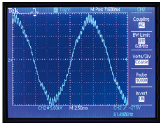
Waveform of power output by conventional generator. Note the frequency error and noticeable distortion
Measured on an oscilloscope (pictured above), its’ sine wave appears jagged. Those small spikes in the sine wave indicate noise that can cause HMI lights to act erratically and cause problems for sophisticated electronics, like video cameras, monitors, computers, and hard drives that need a clean sine wave to operate. With the increasing use of personal computers and microprocessor-controlled recording equipment in motion picture production, the demand for clean, reliable power has reached new heights.
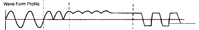
ILLUSTRATION COURTESY OF HARRY BOX
Step 1: Rectifier Bridge converts multi-phase AC power to rectified sine wave. Step 2: rectified sine wave is flattened to DC.
Step 3: micro processor switching alternates wave polarity creating a modified square wave.
Inverter generators meet this demand for cleaner power by adding an additional component that completely processes the “dirty” AC power from the generator’s alternator. An inverter
module takes the raw power produced by the alternator and passes it through a microprocessor controlled multi-step process to condition it. But, rather than using simple two pole cores,
the alternators of inverter generators use multi-pole cores and small stators to produce a raw AC power that is multiphase (more than 300 overlapping sine waves), high frequency
(up to 20’000 Hz), and upwards of 200 Volts. This high voltage AC power is then converted to DC. Finally the DC power is converted back to low voltage single phase AC power by an inverter.
In the process the inverter cleans and stabilizes the power.
Not all inverter generators are equal (Modified square wave verses true sine wave inverters.)
There are 3 major types of inverters used in generators - sine wave, modified square wave, and square wave. One might wonder why there are so many types of inverters.
As John De Armond, explains in his informative article "The “Hows” and “Whys” of Inverters and Inverter Generators" the primary reason is cost. To paraphrase John's article,
to make a nice sine wave from DC power is expensive. There is a trade-off between cost and waveform purity. An approximation of a sine wave
may be created by outputting one or more stepped square waves with the amplitudes chosen to approximate a sine (a modified square wave). The more steps, the more like a
sine wave the output is. However, each of the voltage steps requires its own voltage supply, its own transistor switch, plus the necessary control circuitry. The bottom
line is that the more steps, the more expensive the inverter. The two go hand in hand.
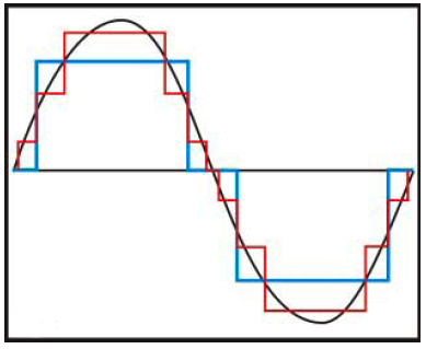
ILLUSTRATION COURTESY OF JOHN DE ARMOND
Ideal Sine Wave (black), Single Step Square Wave (blue),
Three Step Square Wave (red)
Take a look at the figure above. The black trace is, of course our ideal true sine wave. The blue wave is a single step approximation or square wave. The red wave is a three step wave or modified square wave. As is intuitive, the three step wave produces a closer approximation of a sine wave and thus will satisfactorily operate more devices than the single step one. The tradeoff is cost and complexity

ILLUSTRATION COURTESY OF JOHN DE ARMOND
Switch sequence of three step output stage of a modified square wave inverter.
The figure above is a line drawing of a typical three step output stage of a modified square wave inverter. The voltages V1 through V3 are increasingly higher DC voltages
converted from the AC power generated by magnetic induction. A microprocessor generates the pseudo sine wave (modified square wave) by sequentially switching S1 through
S3 on, S3 through S1 off, S4 through S6 on, S6 through S4 off. It repeats this 60 times a second. Where each of the voltage steps requires its own voltage supply, its
own transistor switch, plus the necessary control circuitry, one can intuit that the more steps in the modified square wave, the more complicated and thus more expensive
the inverter is.
Where it is less expensive to make a modified square wave that will satisfactorily operate most construction equipment and RV appliances, than it is to make a true sine
wave there is not the cost/benefit return to warrant the incorporation of the more expensive true sine wave inverters in generators manufactured for these markets. This is
why there are still three types of inverter generators available on the market to this day.
Advantages and Disadvantages:
Square Wave Generators
While a square wave inverter will run simple things like tools with universal motors with no problem, they will not operate much else. For this reason, generators with square wave
inverters are now found only in the construction trades, where they offer the benefit of being cheaper, smaller, lighter, and running longer on a gallon of gas than conventional
generators. For reasons I will explain below, square wave inverter generators have no application in motion picture production.
Modified Square Wave Generators
“Modified Sine Wave”, “Psuedo Sine Wave”, and “Cycloconverter” are all sales terms used for a modified square wave type of AC power. Modified square wave inverters are low in cost, slightly more efficient than conventional generators, and will satisfactorily operate almost all common household appliances and power tools. For this reason, they are typically used in the economy RV/Residential Standby and Industrial lines of generator manufacturers.

Honda EB3000 Cycloconverter Generator
Where the modified square wave is generated from switching DC power that is converted from the AC power the alternator generates, the power MSW Inverter generators generate is cleaner
and more stable than AVR generators. With a slight voltage waveform distortion, MSW Inverter Generators will interact reasonably well with HMI and Kino Flo ballasts. However, a
modified square wave will cause sensitive electronic equipment (computers, hard drives, video cameras) to overheat. While, equipment that depends on peak voltage (battery chargers)
will not operate as effectively on a modified square wave. For these reasons MSW Inverter Generators are less than ideal for HD digital cinema productions. John De Armond, clearly explians
why that is the case using one of the more rudimentary inverter generators, the simple three step modified square wave discussed above, as an example in his article
"The “Hows” and “Whys” of Inverters and Inverter Generators".
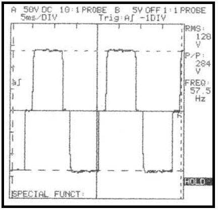
ILLUSTRATION COURTESY OF JOHN DE ARMOND
Output waveform of a Honda EX350 square wave inverter generator
The photo above is an oscilloscope shot of the actual output of an older Honda EX350 modified square wave inverter generator. Notice the RMS voltage indication on the right side - 120 volts even though the peak voltage is only 142 volts. For a true sine wave, the peak voltage would be 120 * 1.414 = 169 volts. This difference in peak voltage is what makes or breaks the operation of modified square wave inverter generators in motion picture production applications where they work fine on construction sites.
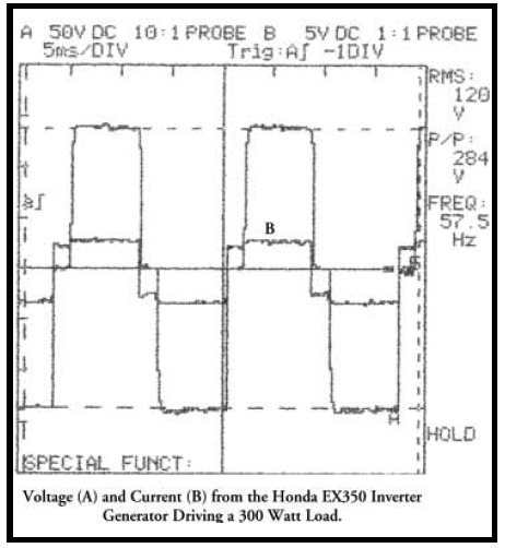
ILLUSTRATION COURTESY OF JOHN DE ARMOND
Voltage and the current output waveforms of a Honda EX350 square wave inverter generator
powering 300W incandescent light
The photo above shows a scope shot of both the voltage and the current output of this generator driving a 300 watt incandescent light (a resistive load.) As you see, a modified
square wave works well for a resistive load like an incandescent light. Things get a whole lot more interesting when one connects a fluorescent lamp to the
generator. As you can see in photo below the solid-state ballast of the fluorescent lamp slightly distorts the voltage waveform (creates a spike) and creates
all kinds of current oscillation. This kind of harmonic activity can cause a noticeable audio buzz, equipment to malfunction, or shut off (more on harmonic noise latter.)

ILLUSTRATION COURTESY OF JOHN DE ARMOND
Voltage and the current output waveforms of a Honda EX350 square wave inverter generator
powering fluorescent light
Another common problem with modified square wave generators like the Honda EX350 is encountered when they are used to charge batteries on remote sets without grid power. John De Armond
illustrates the problem in his informative article "The “Hows” and “Whys” of Inverters and Inverter Generators" by first examining how the battery charger works on grid power when plugged
into a conventional outlet.
To paraphrase him a battery charger typically consists of a transformer, a rectifier and support electronics like charge control circuitry. On each half-cycle of the 60 hz line voltage, the voltage first increases and then decreases in the shape of a sine. The transformer secondary of the battery charger follows this voltage. Connected to the secondary is the rectifier that converts the AC to DC for battery charging. Only when the instantaneous AC voltage exceeds the battery voltage plus the 0.7 voltage drop of the rectifier does current flow to charge the batteries. Photo 5 illustrates this effect. The two lines at “1” and “2” mark on the voltage sine wave where the rectifier starts conducting and causing current to flow.

ILLUSTRATION COURTESY OF JOHN DE ARMOND
Problems arise when a charger of this type is connected to a modified square wave inverter. Recall from the first photo above that the peak voltage of a modified square wave
does not rise as high as a sine wave (142 volts verses the 169 volts of a true sine wave.) The horizontal line in the photo above shows about where the square wave would reach. In
this particular case, the square wave would never reach a voltage sufficient to make the rectifier conduct and so the battery would never charge even though power is connected, the LED indicators light up, and a true RMS voltmeter would indicate about 120 volts. This is another fundamental problem with modified square wave inverters in production applications.
Audio/video production equipment, computers, and battery chargers require a nearly pure (low distortion) sine wave input. If these devices are to be run from an inverter generator, then the generator’s inverter module must supply a sine wave or something pretty close to it. As discussed, inverters of this sophistication are appreciatively more expensive - from 2 to 3 times - because of the number of and prohibitive cost of high power electronic switch devices and components required. However, recent rapid developments in the field of IGBT (insulated gate bipolar transistors) electronics and miniaturization/mass production of microprocessor based digital control systems have reached the stage that Pulse Width Modulation (PWM) inverter modules are economically viable and affordable. Still not as cheap as modified sine wave inverter modules, generator manufacturers only put Pulse Width Modulation (PWM) inverter modules in their deluxe or Super Quiet product lines. For instance, the Honda super quiet EU series of generators employ Pulse Width Modulation (PWM) inverter modules with a waveform distortion factor of less than 2.5% - which is considerably better than conventional generators and quite often better than what you get out of the wall outlet.
True Sine Wave Generators
Pulse width modulation (PWM) inverters provide a more sinusoidal current and for that reason are commonly called true sine wave inverters. Pulse Width Modulation (PWM) inverters use micro-processor control modules to produce AC power with a "true" sine wave (with full width and amplitude) from high voltage DC power converted from the AC power generated by magnetic induction in the core of the generator. PWM inverters are more efficient and typically provide higher levels of performance.

ILLUSTRATION COURTESY OF KIRK KLEINSCHMIDT
Waveform of power output of PWM inverter generator. Note there no discernable distortion or frequency error.
The "true" sine wave these generators deliver is more suitable for computers, solid-state equipment with built-in computer functions or microcomputer-controlled
functions. Unlike the simple two-pole alternators of AVR generators, an inverter generator uses a core that consists of multiple stator coils and multiple rotor magnets.
Each full rotation of the engine produces more than 300 three phase ac sine waves at frequencies up to 20 kHz, which is considerably more electrical energy per
engine revolution than produced in conventional two pole AVR generators.

PHOTO COURTESY OF SUBARU/ROBIN POWER PRODUCTS
Core parts from PWM Inverter Generator. Note the multiple windings of the core stator.
The power generated by the multi-pole core next goes to the inverter module. A basic PWM inverter consists of a converter, DC link, control logic, and an inverter.

Basic wiring schematic of PWM Inverter
The converter section consists of a fixed diode bridge rectifier
which converts the more than 300 three phase ac sine waves at frequencies up to 20 kHz to a DC voltage (about 200 V in at least one unit).

Converter and DC Link
AC Output is then generated from the high voltage DC by the inverter section with voltage and frequency set by a PWM control logic. A
highspeed microprocessor switches IGBTs (insulated gate bipolar transistors) on and off several thousand times a second according to the PWM control logic to
create a variable voltage and frequency.

Control logic and Inverter Section
PWM inverter control logic goes something like this: to generate the positive half cycle of a true AC sine wave, an IGBT connected to the positive value of the DC voltage from the converter is switched on and off by a micro-processor at variable rates and for variable intervals to create current to flow of a variable voltage.
ILLUSTRATION COURTESY OF SIEMENS CORP.

PWM Voltage and Current
In other words, the IGBT is switched on for a short period of time,
allowing only a small amount of current to build up and then is switched off. The IGBT is switched on and left on for progressively longer periods of time, allowing current to build up to higher levels until the current reaches a peak. The IGBT is then switched on for progressively shorter periods of time, decreasing current. The negative
half of the AC sine wave is generated by switching an IGBT connected to the negative value of the converted DC voltage. The fixed DC voltage (200 VDC) is modulated or clipped in this fashion to provide a variable voltage and frequency.
Where IGBTs can turn on in less than 400 nanoseconds and off in approximately 500 nanoseconds, they are ideal for the high switching speed necessary to create a true sine wave in this fashion.
The fixed DC voltage (200 VDC) is modulated or clipped in this fashion to provide a variable voltage and frequency.
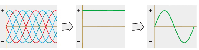
ILLUSTRATION COURTESY OF KIRK KLEINSCHMIDT
The three phases of the inverter generator process: high frequency AC converted to DC; DC inverted to stable clean 120V, 60 Hz AC.
To summarize this complex process: the generator's multi-pole core produces high voltage multiphase AC power. The AC power is then converted to DC. Finally the
DC power is converted back to AC by an inverter. Since the inverter completely processes the raw power generated by the alternator, the voltage and frequency of the power it generates is no longer linked to engine speed (RPM) as is the case with conventional AVR generators.
Rather, using microprocessor controlled IGBTs the inverter module switches the high voltage DC according to PWM control logic to provide AC power with a voltage
stability within ± 1%, and frequency stability within ± 0.01 HZ. The end result is a nearly pure sine wave with a wave distortion of only 2.5%; which, is as clean or cleaner than
commercial power.
As discussed above, developments in this direction began a long time ago, but a techno-economical solution could not be found to manufacture true sine wave inverters until recently because of the prohibitive cost of high power electronic devices and components.
However, recent rapid developments in the field of IGBT electronics and miniaturization/mass production of microprocessor based digital control systems have reached the stage that Pulse Width Modulation (PWM) inverter modules are economically viable and affordable.
As we will see shortly, there is more to inverter generators that make them especially good for motion picture applications, but to understand why, we first must understand the peculiar characteristics of the load that we put on portable generators that a construction contractor does not.

Before we look at different lighting loads, by way of review, I would suggest watching a very informative You Tube video titled “Inside an Inverter Generator, Car Alternator, AC." Produced by Green Power Science, whose mission is “Free Power For The World Through Creative Thinking”, the video surveys alternate types of generators that can be used with wind turbines, ranging from car alternators to fan motors, but begins with a very good “under the hood” look at the difference between conventional AVR generators and Inverter generators. The video is available online at http://www.youtube.com/watch?v=0TG2uZfE-PQ.
__________________________________________________________________
Lighting Load Types
All loads are not created equal
All lighting loads are not the same. Incandescent, Fluorescent, LED, and HMI lights fall into two broad categories. Those that are linear loads and those that are non-linear
loads. Non-linear loads further break down into two categories: those that exhibit high inductive reactance (magnetic HMI ballasts) and those that exhibit high capacitive
reactance (electronic HM, Fluorescent, & LED ballasts). Because each type of load has an effect (mostly adverse) on the power supply, their individual characteristics are worth
exploring in more detail. Even more so, because they adversely affect generated power more than they do grid power.
Linear Loads
Incandescent Lights (Purely Resistive Loads)
An incandescent light is a simple resistive load. The high resistance of its tungsten filament creates heat until the filament glows - creating light. The current in such a simple
resistive AC circuit increases proportionately as the voltage increases and decreases proportionately as the voltage decreases. Changes in alternating current (AC) and the
relationship between voltage and current in a purely resistive circuit (Incandescent Lights) can be represented graphically by the sine waves below.

Unity Power Factor: Voltage & Current are in Phase.
For a sinusoidal voltage, the current is also sinusoidal. For a purely resistive load like incandescent lights, the current is always proportional to the voltage. The voltage and current are in phase and so have a Power Factor of 1 or unity power factor (power factor will be explained in detail below.)
Non-Linear Loads
HMI Lights with Magnetic Ballasts
The make up of a magnetic HMI ballast is relatively simple by comparison to the newer electronic HMI ballasts. Between the power input and the lamp is a transformer that acts as a choke coil. The transformer provides the start-up charge for the igniter circuit, rapidly increasing the potential between the electrodes of the head’s arc gap until an electrical arc jumps the gap and ignites an electrical arc between the lamp electrodes. The transformer then acts as a choke, regulating current to the lamp to maintain the pulsating arc once the light is burning.
As such, the light intensity of an HMI follows the power waveform and increases and decreases 120 times a second, twice every AC cycle. This fluctuation is not visible to the eye but will be captured on film or video as a steady pulsation if the camera is not in precise synchronization with the AC power frequency. With magnetic HMI ballasts, to avoid this flicker, you must use a crystal controlled camera, run the camera at one of a number of safe frame rates (those that can be divided into 120 and result in a whole number), and use power that is regulated at exactly 60 Hertz (cycles per second.)

Transformers of a 12k Magnetic HMI Balllast
Essentially a large coil of wire that is tapped at several places to provide for various input voltages and a high start-up voltage, the transformers of magnetic HMI ballasts
exhibit high self-inductance. Self-inductance is a particular form of electromagnetic induction that inhibits the flow of current in the windings of the ballast transformer,
pulls the voltage out of phase with the current, and reduces the power efficiency (power factor) of the ballast. Because the high self-inductance inherent in magnetic HMI
ballasts adversely effects the power generated by small portable generators, it is a topic worth exploring in more detail.
Self-Inductance
Self-inductance is defined as the induction of a voltage in a current-carrying wire within a coil when the current in the wire itself is changing as it
alternates. Taking a close look at a simple circuit with a coil will help us to understand how voltage is induced by changing current. The alternating
current running through a coil creates a magnetic field in and around the coil that is increasing and decreasing as the current alternates. The magnetic
field forms concentric loops that surround the wire and join to form larger loops that surround the coil as shown in the image below. When the current
increases in one loop the expanding magnetic field will cut across some or all of the neighboring loops of wire, inducing a voltage in these loops. This
voltage causes a current to flow in the windings of the coil.
ILLUSTRATION COURTESY OF THE NDT RESOURCE CENTER
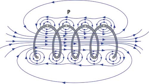
Magnetic fields created in and around a coil with alternating current running through it.
By studying this image of a coil, it can be seen that the number of turns in the coil will have an effect on the amount of voltage that is induced into our
simple circuit. Increasing the number of turns or the rate of change of magnetic flux thereby increases the amount of current induced. The current induced
by this voltage has a direction such that its magnetic field opposes the change in magnetic field that induced the current. Or, in other words, the current
induced in a conductor will oppose the change in current that is causing the flux to change.
Inductive Reactance
By taking an even closer look at a coil of wire it can be seen how induction reduces the flow of current in our simple circuit. In the image below, the direction of the primary current is shown in red, and the magnetic field generated by the current is shown in blue. It can be seen that the magnetic field from one loop of the wire will cut across the other loops in the coil and this will induce current flow (shown in green) in the circuit.
ILLUSTRATION COURTESY OF THE NDT RESOURCE CENTER

Induced current works against the primary current in a coil.
Note that the induced current flows in the opposite direction of the primary current and accomplishes no actual work other than to create energy circulating back and forth between the coil and the power source. The induced current working against the primary current results in a reduction of current flow in our simple circuit. This opposition to the flow of current is called inductive reactance.
Since inductive reactance reduces the flow of current in a circuit, it appears as an energy loss just like resistance. However, it is possible to distinguish between resistance and inductive reactance in a circuit by looking at the timing between the sine waves of the voltage and current of the alternating current. As we saw above, in AC circuits with resistive loads, the voltage and the current are in-phase, meaning that the peaks and valleys of their sine waves occur at the same time. When there is inductive reactance present in the circuit, the phase of the current will be shifted so that its peaks and valleys do not occur at the same time as those of the voltage. As illustrated below, inductive reactance causes current to lag behind the voltage. The degree to which the two waveforms are put out of phase depends on the relative amount of resistance and inductance offered by the coil.

Poor Power Factor: Voltage & Current are in out of phase.
As we saw in our simple circuit above, the number of turns in the coil will have an effect on the amount of voltage that is induced into the circuit. Increasing the number
of turns increases the amount of induced voltage. In the case of a magnetic HMI ballast, the multiple fine windings of the ballast transformer induces appreciable voltage
and considerable current that is in opposition to the primary current, causing the primary current to lag behind voltage, a reduction of current flow, and an inefficiency
in the use of power supplied by the generator. Put simply, the ballast draws more power than it uses to create light. Capacitors are typically included in the design of
magnetic HMI ballasts to compensate for the high inductance of the transformer and to bring the current back in phase with the voltage.
Apparent Power Verses True Power = Power Factor
If, in this situation, you were to measure the current (using a Amp Meter) and voltage (using a Volt Meter) traveling through the cable supplying the magnetic HMI ballast and multiply
them according to Ohm’s Law (W=VA) you would get the “Apparent Power” of the ballast (expressed as KVA.) But, if you were to instead, use a wattmeter to measure the actual amount of energy
being converted into real work (light) by the ballast, after the applied voltage overcomes the induced voltage, you would get the “True Power” of the ballast (expressed as KW.) The difference
between Apparent Power and True Power, or the additional power required for the applied voltage to overcome the induced voltage, is the Reactive Power (expressed as KVAR.) The ratio of
True Power to Apparent Power is called the “Power Factor” of the ballast.
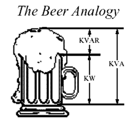
The favorite analogy electricians like to use to explain these terms is that if Apparent Power is a glass of beer, Reactive Power is the foam that prevents you from filling it up all the way, so
that you are left with less beer or Ture Power. In other words, the thirst-quenching portion of your beer is represented by KW in the figure above. The foam is represented by KVAR. The total
contents of your mug, KVA, is this summation of KW (the beer) and KVAR (the foam). In our beer mug analogy, Power Factor (P.F.) is then the ratio of Beer (True Power) to the entire volume of the mug (beer plus foam or Apparent Power.)

Thus, for a given KVA: the more foam you have (the higher the percentage of KVAR), the lower your ratio of KW (beer) to KVA (beer plus foam). Thus, the lower your power factor. Or, the less foam you have (the lower the percentage of
KVAR), the higher your ratio of KW (beer) to KVA (beer plus foam). In fact, as your foam (or KVAR) approaches zero, your power factor approaches 1.0. When lights with a low power factor are used, a generator must be sized to supply the apparent power (beer plus foam), even though only the beer (true power) counts as far as how much actual
drinking is possible.
Our beer mug analogy is a bit simplistic. In reality, when we calculate KVA, we must determine the “vectorial summation” of KVAR and KW.
Therefore, we must go one step further and look at the angle between these vectors.

To understand this concept let’s use the analogy of a man dragging a heavy load as illustrated above. The man’s Working Power (or True Power) in the forward direction, where he most wants his load to
travel, is KW. Unfortunately, the man can’t drag his load on a perfect horizontal (he would get a tremendous backache), so his shoulder height adds a little Reactive Power, or KVAR. The Apparent Power the man is dragging, KVA, is this “vectorial summation”
of KVAR and KW. The “Power Triangle” below illustrates this relationship between KW, KVA, KVAR, and Power Factor:
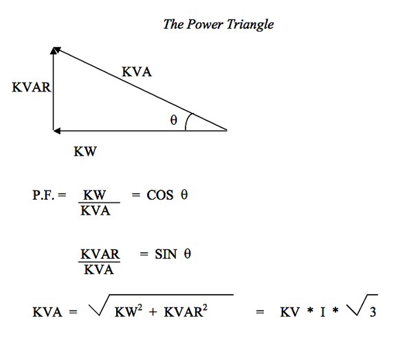
In an ideal world (one without gravity), the man wouldn’t have to waste any power along his body height and so the KVAR would be very small (approaching zero.) KW and KVA would be almost equal and so the angle & (formed between KW and KVA) would approach
zero and the Cosine & would then approach one. Power Factor would then approach one. For a light to be considered “efficient”, the Power Factor should be as close to 1.0 as possible. Where a typical 1200W
magnetic HMI ballast takes 13.5 Amps at 120 Volts ( KVA =13.5A x 120V= 1620W), to generate 1200 Watts of light (KW), our 1200W magnetic ballast wastes roughly 25% of the power that it uses in Inductive Reactance.
Capacitive Reactance
Electronic HMI, Fluorescent, & LED ballasts belong to a category of power supplies, called Switch Mode Power Supplies (SMPSs), that waste power in another way - one called Capacitive Reactance. SMPSs utilize electronic components that use only portions of the AC power waveform. These devices then return the unused portions as harmonic currents that stack on top of one another, pull the voltage and current out of phase, and under the wrong conditions create distortion of the voltage waveform.

As illustrated in the wiring schematic above, all SMPSs consist of first a diode-capacitor section (consisting of a Bridge Rectifier and Smoothing
Capacitor) that converts the AC input power to DC power; and then, in the case of HMI & Fluorescent lights, a Switch-mode Converter section that converts the DC power back
to an alternating power waveform that ignites the lamp. In the case of High Output AC LED ballasts, the Switch Mode Converter further conditions the DC power the diode-capacitor section outputs. How HMI and Fluorescent ballasts differ as SMPSs is by the shape and frequency of the alternating power waveform the Switch-mode converter
generates. In the case of electronic HMI ballasts the Switch-mode converter generates a low frequency (60Hz) square wave. In the case of electronic Fluorescent ballasts,
the Switch-mode converter generates a high frequency (>20kHz) sine wave.
Regardless of what circuits are in the green box in the illustration above, all SMPSs utilize a diode-capacitor
section to first convert the AC line input power to DC power. The diode-capacitor section of a SMPS is the source of the capacitive reactance that opposes the flow of current
and contributes to its’ poor power factor.
ILLUSTRATION COURTESY OF HARRY BOX

The capacitive reactance of SMPSs act on power in a way opposite to inductive reactance. It causes current to lead voltage. SMPSs typically have a power
factor less than .6, meaning that the ballast (whether HMI, Fluorescent, or LED) has to draw 40% - 50% more power than it uses. Where capacitive reactance
leads to an inefficient use of power (lots of foam, not much beer), and the harmonic currents generated can have adverse effects on other equipment
operating on the same power, it is worth exploring the cause of capacitive reactance and the source of the harmonic currents in more detail.
To understand the cause of the capacitive reactance of SMPSs, and it’s effect on the power supply, let’s look first at the operation of fluorescent
ballasts in more detail.
Fluorescent Lights (Electronic vs. Electromagnetic Ballasts)
The ballast of a fluorescent light functions very much like an HMI ballast. It provides the lamp with high voltage during start-up to ignite an arc between the lamp electrodes, and then stabilizes the arc by limiting the electrical current to the lamp. As in the case of HMI lights, there are two basic types of fluorescent ballasts: magnetic and electronic.
A magnetic fluorescent ballast works very much like a magnetic HMI ballast. It uses a magnetic transformer of copper windings around a steel core to convert the input line voltage and current to the voltage and current required to start and operate the fluorescent lamp. Like magnetic HMI ballasts, they exhibit high inductive reactance and have a poor power factor. The power factor of magnetic ballasts is usually less than .5 and they typically account for 18% to 35% of total harmonic distortion in the power supply of offices where they are commonly used. Like magnetic HMI ballasts, the output frequency of a magnetic fluorescent ballast is the same as the input AC line frequency (60 Hz), which means that (as was the case with an HMI magnetic ballast) the camera frame rate must be synchronized with the AC frequency of the power supply in order to avoid the appearance of light intensity fluctuation in the image.
For this reason fluorescent lights were seldom used in motion picture production until the advent of high frequency electronic ballasts for fluorescent lamps.
Fluorescent Lights with Electronic Ballasts
Electronic fluorescent ballasts are a Switch-mode Power Supply (SMPS) designed to perform all the same functions as a magnetic ballast but at a higher frequency. They first rectify the 60 Hz AC input to DC and then produce a very high frequency alternating current (20,000 - 50,000 Hz depending on the fixture) using an inverter and power conditioning components.

Kino Flo 4 Bank Select Ballast
The high frequencies at which electronic fluorescent ballasts operate make them a suitable light source for film and television production. By converting the 60 Hz input frequency to between 20,000 - 50,000 Hz, electronic ballasts eliminate the problem of light intensity fluctuation associated with standard magnetic ballasts. At those frequencies the period of time between the off and on pulse of each cycle is so short that the illuminating phosphors do not decay in light output.

Assorted High Frequency Fluorescent Lights Designed for Motion Picture Lighting.
Like the glowing tungsten coil of an incandescent lamp, the fluorescent phosphors become essentially flicker free. Electronic fluorescent ballasts also weigh less and don’t have the characteristic hum of magnetic ballasts. These characteristics of high frequency electronic ballasts make them well suited for motion picture lighting. Developed first by Kino Flo (above), and now available from a number of manufacturers, motion picture fluorescent lights now come in a wide assortment of shapes and sizes.

Assorted CFL Fluorescent Lights Designed for Motion Picture Lighting.
Regardless of its’ shape or size, the ballasts of all high frequency fluorescent lights utilize a Diode-Capacitor circuit to first convert the AC line input to DC. Since it is the Diode-Capacitor circuit of an electronic ballast that generates a high level of capacitive reactance, which leads to an inefficient use of power and the generation of harmonic currents, let us examine how they work in one type of fluorescent light in more detail – the self ballasted Compact Fluorescent Lamp (CFL) pictured below.

CFL Fluorescent Light being tested.
Since the Diode-Capacitor circuit of a self ballasted CFL is similar in design to those in most all fluorescent movie lights (Kino Flo, Lowel, etc.), a close examination of the power factor of CFLs will help us to understand the cause of the capacitive reactance in SMPSs in general, as well as it’s effect on the power supply.

circuit schematic of an Incandescent bulb.
To understand the power factor of a self ballasted CFL bulb it is helpful to compare it to an incandescent bulb. If you will recall from the beginning of
this section, an incandescent light is a simple resistive load (see circuit schematic above.) The high resistance of its tungsten filament creates heat until the filament glows - creating
light. As we see in the oscilloscope shot below, of a 25W incandescent bulb operating on grid power, the current is always proportional to the voltage (current is represented on the scope as the voltage drop on a 1 Ohm resistor.)

Current and Voltage Waveform of a ACEC 25W Incandescent bulb.
If the applied voltage is sinusoidal, the current generated is also sinusoidal. That is, the current increases proportionately as the voltage increases and decreases proportionately as the voltage decreases. Since the peak of the voltage corresponds to the peak in current, the voltage and current are also in phase and so have a unity power factor (Power Factor of 1.)
The voltage and current waveforms, below, of a CFL bulb operating on grid power is very different from that of the incandescent light above. The most
noticeable difference is that the current, generated by the CFL bulb, no longer proportionately follows the nice smooth sinusoidal voltage waveform
supplied to it by the power grid. Rather, it has been distorted by electrical components in the ballast so that it instead consists of sharp spikes
in power that quickly drop off over a short duration. A second distinguishing characteristic is that the peak of the voltage no longer corresponds
to the peak in current. The current now “leads” the voltage by 1.7 milli seconds. The voltage and current are no longer in phase, but instead exhibit
what we call a Leading Power Factor.

Current and Voltage Waveform of a Brelight 25W CFL Bulb.
Like all electronic fluorescent ballasts, the ballasts of CFLs are a Switch-mode Power Supply that converts line-frequency power (60Hz) to a high frequency alternating current.
In the case of self-ballasted CFL bulbs, what is in the green Switch Mode Converter box of the SMPS illustration above, are a pair of MOSFETS (metal–oxide–semiconductor
field-effect transistors) that act as a high frequency DC to AC inverter.
For the purpose of this discussion, what's in the green Switch Mode box, or what the power supply ultimately does with the DC power put out by the diode-capacitor circuit is not
important. What's important is that like all SMPSs, CFL ballasts consist of first a diode-capacitor section that converts the AC input power to DC power. Since, the
capacitive reactance of all SMPSs is caused by this diode-capacitor circuit, how it operates in self-ballasted CFL bulbs and the affect it has on power quality is
representative of SMPSs in general (fluorescent, HMI, & AC LED.)
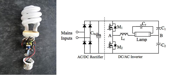
Typical schematic of CFL electronic ballast: L-to-R consists of half-bridge rectifier, conditioning capacitor, DC/AC Inverter.
The distorted current waveform and Leading Power Factor exhibited by CFLs is caused by the Diode-Capacitor circuit of its’ electronic ballast. To quickly
summarize the cause of this current distortion, the Diode-Capacitor circuit uses only the ascending portion of the supply voltage waveform - which pulls
the current out of phase with the voltage. As seen in this scope shot, it also draws current in quick
bursts, and returns the unused portions as harmonic currents that stack on top of one another creating harmonic distortion of the power waveform.
These harmonic currents, combined with the Leading Power Factor, creates the capacitive reactance that opposes the flow of current in the circuit that
leads to an inefficient use of power by the ballast. Since, the harmonic currents generated can have an adverse effect on other equipment operating on
the same power, it is worth exploring the cause of this capacitive reactance and the source of the harmonic currents in more detail.

Step 1: Rectifier Bridge converts line frequency AC power to rectified sine wave. Step 2: rectified sine wave is flattened to DC by conditioning Capacitor.
Step 3 (not shown): Inverter alternates wave polarity creating a high frequency alternating power to excite lamp gases.
As illustrated above, the diode-capacitor section converts the AC power to DC power by first feeding the AC input current through a bridge rectifier,
which inverts the negative half of the AC sine wave and makes it positive. The rectified current then passes into a conditioning capacitor that
removes the 60 Hz rise and fall and flattens out the voltage - making it essentially DC. The DC is then fed from the conditioning capacitor to the
Switch-mode converter which in the case of a fluorescent ballast is a high frequency inverter that utilizes a pair of MOSFETs to generate the high frequency (20-50kHZ) AC power.

Yellow Trace: Rectifier Bridge converts AC power to rectified sine wave. Blue Trace: Stored Capacitor Voltage. Red Trace: Current drawn by capacitors once input voltage is greater than voltage stored in the capacitor (Blue trace.)
As shown in the illustration above, the diode-capacitor circuit only draws current during the peaks of the supply voltage waveform as it charges the
conditioning capacitor to the peak of the line voltage. Since the conditioning capacitor can only charge when input voltage is greater than its stored
voltage, the capacitor charges for only a very brief period of the overall cycle time. That is because, after peaking, the half cycle from the bridge
drops below the capacitor voltage; which back biases the bridge, inhibiting further current flow into the capacitor. Since, during this very brief
charging period, the capacitor must charge fully, large pulses of current are drawn for short durations. Consequently, electronic fluorescent ballasts
(and SMPSs in general), draw current in high amplitude short pulses. The remaining unused current feeds back into the power stream as harmonic currents.
Given this method of operation, the diode-capacitor circuits of CFLs (and SMPS in general) create two artifacts that can effect power quality adversely. First,
since the conditioning capacitor starts to charge when input voltage is greater than its stored voltage, and stops after the input voltage peaks,
it pulls current out of phase with voltage. As we can see in the oscilloscope shot above, it causes current to lead voltage or creates a "Leading Power Factor."
Second, the unused portions of the voltage waveform that return into the power stream as harmonic currents can have a severe effect on power quality under certain conditions.
Where, it is the combination of a Leading Power Factor and harmonic currents generated by diode-capacitor circuits that constitute the capacitive reactance of SMPS that
opposes the flow of current it is worth exploring the effect of both in CFLs in more detail.

Components of a CFL ballast
These simple diode-capacitor circuits are used in CFL bulbs and in many fluorescent movie lights because they are compact and inexpensive. However, they have a number of
drawbacks. For instance, notice how large the input current spike (red trace above) of the diode-capacitor circuit is. Without power factor correction, the in-put bridge
rectifier requires a large conditioning capacitor at its output. This capacitor results in line current pulses (as seen in our oscilloscope shot above) that are very high
in amplitude. All the circuitry in the ballast as well as the supply chain (the generator, distribution wiring, circuit breakers, etc) must be sized to carrying this high
peak current (the foam in our analogy).
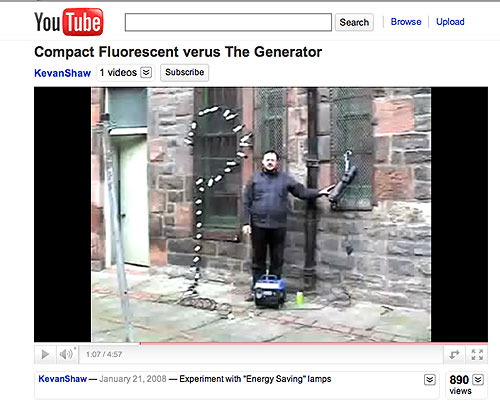
For a rather amusing demonstration of the greater current drawn by SMPSs for the same wattage of light check out this You-Tube video
“Compact Fluorescent
verses The Generator." In this video, lighting designer Kevan Shaw, first operates a 575W ETC Source Four Leko with
Quartz Halogen bulb on an 850W two stroke gas generator without problem. However, when he tries to operate an equivalent wattage of CFLs (30 x 18W bulbs = 540W) the generator goes
berserk. Kevan then turns off the 18W CFL bulbs one at a time until the generator stabilizes. Only after turning off half the CFL Bulbs does the generator operate normally
with a remaining load of 15 - 18W CFLs (270 W.) What accounts for the erratic behavior of the generator in this video under the smaller load of CFLs? It is a combination of the
poor Power Factor of the CFL bulbs and the harmonic currents they generate. Even though the 15 CFL bulbs have a True Power of 270W, the Watt indicator on Kevan's generator
indicates that they draw twice that in Apparent Power (535W), or have a Power Factor of .5 (270W/535W =.504.)
Another drawback to the diode-capacitor circuits used in SMPSs is that when they draw current it is for only a fraction of the half cycle of the voltage waveform.
If we return to the illustration above, we see that the pulses of current are narrow, with fast rise and fall times. Since a diode-capacitor circuit uses only the very
peak of the voltage waveform, they generate high harmonic content as the unused portions of the voltage waveform are returned as harmonic currents (see graph below.)

Distribution of Harmonic Currents generated by CFL bulb
The fast rise time of these current pulses can cause Radio Frequency Interference (RFI) problems. For this reason, Lowel Light warns on their website that their compact fluorescent (CFL) fixture, the Lowel Ego, that: “The lamps may cause interference with radios, cordless phones, televisions, and remote controls. If interference occurs, move this product away from the device or move to a different outlet” (http://www.lowel.com/ego/lamp_info.html.)
Harmonic currents can also stack on top of one another creating excessive current on the distribution system neutral (see below.) And, since the neutral conductor of a distribution system is not fused, it can cause the neutral to overheat and possibly catch fire.

In one study, substituting incandescent lamps with the equivalent wattage of CFLs in a small single phase distribution system
substantially increased the current on
the system neutral as a result of the 3rd harmonics generated by the CFL Bulbs.
For this reason, on their website Kino Flo cautions users of their older style fixtures, that the ballasts “will draw double the current on the neutral from what is being drawn on the two hot legs. On large installations it may be necessary to double your neutral run so as not to exceed your cable capacity.” (http://www.kinoflo.com/FYI/FAQs.htm#2"]FAQ “Why is the neutral drawing more than the hot leg.”)
Finally, when the power is supplied by a conventional AVR generator, these harmonic currents can also lead to severe distortion of the voltage waveform in the power distribution
system. When you plug an electronic ballast (fluorescent, HMI, or LED) into a wall outlet you need not be concerned about current harmonic distortion producing voltage distortion.
The impedance of the electrical path from the power plant to the outlet is so low, the distortion of the original applied power waveform so small (less than 3%), and the power
plant generating capacity so large by comparison to the load, that harmonic currents fed back to it will not effect the voltage at the load bus (electrical outlet.) However,
it is an all together different situation when plugging an electronic ballast (fluorescent, HMI, or LED) into a portable generator. In this case, the impedance of the power generating
system (generator and distribution cable) is sufficient enough that a harmonic current will induce a voltage at the same frequency. For example, a 5th harmonic current will
produce a 5th harmonic voltage, a 7th harmonic current will produce a 7th harmonic voltage, etc. Since, as we saw above, a distorted current waveform is made up of the
fundamental plus one or more harmonic currents, each of these currents flowing through an impedance will, result in voltage harmonics appearing at the load bus, a voltage
drop, and distortion of the voltage waveform.
Since electronic ballasts consume current only at the peak of the voltage waveform (to charge the smoothing capacitor), voltage drop due to system impedance occurs only at the peak of the voltage waveform. In this fashion, the pulsed current consumed by electronic ballasts produces voltage distortion in the form of flat-topping of the voltage waveform.

The pulsed current consumed by electronic ballasts produce voltage distortion in the form of flat-topping
The measurement of this distortion is designated as the Total Harmonic Distortion (THD) of the distribution system. While self ballasted CFLs generate the most severe harmonic
noise, all fluorescent ballasts (both magnetic & electronic) generate harmonic noise (see table below.)

The severe voltage waveform distortion exhibited above can cause overheating and failing equipment, efficiency losses, circuit breaker trips, and instability of the generator's
voltage and frequency. In addition to creating the radio frequency interference (RFI) mentioned on the Lowel Light website, harmonic distortion of this magnitude can also
cause component level damage to HD digital cinema production equipment and create ground loops. We will explore how harmonic distortion of the power waveform
adversely effects equipment operating on it in more detail in subsequent sections, but first lets continue our survey of lighting loads with electronic HMI ballasts.
HMI Lights with Electronic Ballasts
Like the development of electronic fluorescent ballasts, the development of electronic HMI ballasts was a major advance in lighting technology because they eliminate the flicker problem associated with magnetic ballasts, as well as the need for expensive frequency governors in small generators. They allow you to film at any frame rate and even at changing frame rates. An electronic HMI ballast eliminates flicker by creating a virtually constant output of light over the AC cycle by squaring off the curves of the AC sine wave. The changeover period is so brief that the light is virtually continuous.

By comparison to magnetic HMI ballasts, electronic HMI ballasts are quite a bit more complicated. As another example of a Switch-mode Power Supply (SMPS),
they, in fact, operate in a very similar fashion to electronic fluorescent ballasts. Like a fluorescent ballast, AC power is first converted into DC.
Then, a high-speed switching device (micro processor controlled IGBTs) turns the DC current into alternating current. The difference between an
electronic HMI ballast and an electronic fluorescent ballast is that the HMI ballast generates a square wave where the electronic fluorescent ballast
generates a high frequency sine wave.

Since an electronic ballast completely processes and regulates the input power they can tolerate fairly wide voltage and Hertz rate discrepancies. A 120V
electronic ballast can take an input from 95V to 132V with out affecting the output signal and the fixture's color temperature, and it will not be
affected by the fluctuations in frequency (Hz) of conventional AVR generators without governors.
Where they are not frequency dependent and will tolerate voltage fluctuations, at first it was thought that electronic square wave ballasts would operate
more reliably on small portable generators – even those without frequency governors. For this reason, as soon as electronic square wave ballasts appeared
on the market, many lighting rental houses replaced the more expensive crystal governed portable generators with less expensive non-synchronous portable
generators. The theory was that an electronic square wave ballast would operate reliably on a non-synchronous generator and allow filming at any frame rate, where as a magnetic HMI ballast operating on a crystal controlled synchronous generator allowed filming only at permitted frame rates. In practice, electronic square wave ballasts turned out to be a mixed blessing.
Like all SMPSs, electronic HMI ballasts without Power Factor Correction draw current in large pulses and return harmonic currents to the power stream. The capacitive reactance of electronic HMI ballasts also causes current to lead voltage and so they also have a
leading Power Factor. A non-Power Factor Corrected (non-PFC) square wave HMI ballast typically has a Power Factor less than .6, meaning the ballast has to draw 40 percent or more power than it uses. Exactly how much current a ballast will draw is indicated in the electrical specifications
on the manufacturer’s nameplate. Let’s take a look at one of these nameplates, since deciphering them can be as difficult as deciphering Egyptian Hieroglyphs if you don’t know how to read them. It doesn’t help that the ballasts are made in Germany and include the
scientific symbols for Voltage, U instead of V, and Current, I instead of A for Amperes.
Below is the nameplate from an Arri non-PFC 575/1200 Electronic Ballast. The first thing to look for is the ballast’s Apparent Power, which is called “Pmax” here, and expressed in Volt-Amperes (VA). Calculated as the RMS voltage times the current measured at
the input to the device, Volt-Amperes is
the measurement of Apparent Power drawn by the ballast, which is different than Wattage. Wattage is the True Power dissipation of the lamp calculated by integrating the product of current through the lamp and voltage over time. These may sound like they would be
the same (they are in the case of incandescent lamps), however like Fluorescent and LED power supplies, HMI ballasts discharge back into the power line some of the current flowing into them in the form of harmonic currents. As was the case with Magnetic HMI ballasts, the relationship between True and Apparent Power is the Power Factor (PF.) Since, the Wattage will always be lower than or equal to the Volt-Amperes, PF varies from 0.0 to 1.0.

As indicated on the nameplate above, this ballast has an Apparent Power of 2290VA - which means it draws nearly twice the load of its’ 1200W light output. Next to the Pmax, it also indicates that the Power Factor is .6 (cos@=.6), or that the greater Apparent Power drawn by
the ballast consists not only of high amplitude short pulses of current, but also harmonic currents that the ballast returns into the distribution system.
The next thing to notice is the relationship between Voltage (U) and Current (I). As this nameplate indicates this ballast will operate on line voltages ranging from 90 to 125 volts (US), and 180 to 250 volts (European.) You will also notice that the current (I) the
ballast draws varies with the supply voltage. For example, according to the nameplate it will draw 18A of current (I) at 125 Volts (U) (2290VA/125V = 18.32A.) If the voltage drops to 90V, it will draw over 25 Amps (2290VA/90V = 25.44A.) This is another one of the big
differences between Tungsten lights and HMIs that is important to appreciate. With a drop in voltage the current drawn by a Tungsten light drops in step with the voltage as the light output dims. In the case of HMIs, a drop in voltage causes current to rise in step
and light output remains constant. The reason for this is because, as discussed above, HMI ballasts use capacitors to flatten out a rectified sine wave before converting it to an alternating square wave.
Like all SWMPs, the diode-capacitor section of HMI ballasts (as illustrated above) convert the AC input power to DC power by first feeding the AC input through a bridge rectifier, which inverts the negative half of the AC sine wave and makes it positive. The rectified current then passes into conditioning capacitors that remove the 60 Hz rise and fall and flattens out the voltage - making it DC. The DC is then fed from these capacitors to the power module where the IGBTs switch it into an alternating square wave.
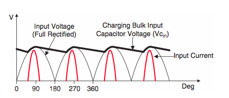
Thin Black Trace: Rectifier Bridge converts AC power to rectified sine wave. Thick Black Trace: Stored Capacitor Voltage. Red Trace: Current drawn by capacitors once input voltage is greater than voltage stored in the capacitor (thick black trace.)
As shown in the illustration above, the diode-capacitor circuit only draws current during the peaks of the supply voltage waveform as it charges the conditioning capacitor to the peak of the line voltage. After 90 degrees, the half cycle from the bridge drops below the capacitor voltage; which back biases the bridge, inhibiting further current flow into the capacitor. Since the capacitors have only a short interval to receive their full charge, they draw current in large pulses (which explains the higher Apparent Power of HMIs.)
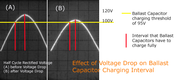
Given how the diode-capacitor circuits of HMI ballasts operate, the effect of voltage drop is to decrease the interval in which the capacitors have to charge. If we compare (in the illustration above) one half cycle of a rectified sine wave at full line level (115V) to one half cycle of a rectified sine wave at 100 Volts, we see that the period during which the capacitors must recharge is appreciably shortened. Given a shorter interval to charge, the capacitors draw current in even higher amplitude bursts. The diode-capacitor circuit therefore works harder, drawing more current during an even briefer charging period, increasing its’ load on the electrical circuit in order to maintain the same Apparent Power. For this reason, electronic HMI ballasts are commonly referred to as “Constant Power” ballasts.
This is an important characteristic of HMI ballasts that should be kept in mind when using 1200W HMIs outside the studio on location. With an Apparent Power of 2290VA, this non-PFC constant power HMI
ballast will operate very close to the threshold of a 20A circuit – too close to operate reliably unless precautions are taken. For example, according to the ballast’s electrical specifications on its’
nameplate, it takes 19 Amps at 120 Volts to generate 1200 Watts of light (2290W/120V = 19A). For this reason, you must dedicate a 20 circuit to this one light. With an Apparent Power of 2290W it will
immediately overload a 15A circuit, and if there is any Line Loss from a long cable run, the ballast will possibly draw over 20 Amps in order to
compensate for the voltage drop and overload a 20A circuit if there is anything else operating on the same circuit. For instance, at 110V it will draw 20.8 Amps. To the problem of line loss, usually there is also increased resistance from an overheated plug end, which makes the
voltage drop even further. Since most stinger plug-ends are only rated for 15 Amps they tend to overheat with 1200W non-PFC electronic ballasts. The increased resistance that results from the heat
causes the voltage to the ballast to drop even further and so it will draw more power to maintain the 2290VA load. If the light is operating on a small generator, there will also be voltage drop
on the generator because of the greater load. The voltage output of generators can drop 5-10 volts under load. At 105V, the ballst that drew 19A at 120V, will now draw 21.8 Amps and likely cause circuit
breakers to overheat and potentially trip.
It is also important to keep in mind that the greater Apparent Power drawn by non-PFC HMI ballasts consist not only of these high amplitude short pulses of current. Like a CFL, a non-PFC HMI
ballast also returns the unused portion of the voltage waveform into the distribution system as harmonic currents. Before exploring in more detail the adverse effect these harmonic currents can have
on generators and equipment operating on the same power, we need to say a few words about the loads placed upon generators by two new light sources: "High Output" AC LEDs and LEPs (Lighting Emitting Plasmas).
High Output AC LEDs

An LED consists of a chip of semiconducting material doped with impurities to create a “p-n junction.” As in other diodes, current flows easily from the p-side, or anode, to
the n-side, or cathode, but not in the reverse direction. As illustrated below, when the opposing electrodes of the p-n junction have different potentials, electrons fall into
the lower energy level, releasing energy in the form of a photons or light. LEDs, by nature, require direct current (DC) with low voltage, as opposed to the mains electricity from the electrical grid that supplies a high voltage with an alternating current (AC).

LED lights used in motion picture lighting applications fall into a category of LED technology called AC LED lighting. The term AC LED lighting refers to illumination generated by High Power LED (HPLED) light engines supplied with a sinusoidal AC voltage source—typically the utility line voltage (e.g., 120 V in the U.S., 100 V in Japan, 220 V in Europe). AC LEDs present many advantages over incandescent light sources including lower energy consumption, longer lifetime, improved robustness, smaller size, faster switching, and greater durability and reliability. For these reasons, but principally because of its high luminous efficacy, AC LED lighting has tremendous potential to become the dominant type of lighting in motion picture production. However, they are relatively expensive and require more precise current and heat management than traditional motion picture light sources.
One of the key advantages of LED-based lighting is its high efficiency, as measured by its light output per unit power input. White LEDs quickly matched and overtook the efficiency of standard incandescent lighting systems. In 2002,
Lumileds made five-watt LEDs available with a luminous efficacy of 18–22 lumens per watt [lm/W]. For comparison, a conventional 60–100 W incandescent light bulb produces around 15 lm/W, and standard fluorescent lights produce up to
100 lm/W. In September 2003, Cree, Inc. introduced a white LED light giving 65 lm/W at 20 mA, becoming the brightest white LED commercially available at the time, and more than four times as efficient as standard incandescent lights.
In 2006 Cree, Inc. demonstrated a prototype with a record white LED luminous efficacy of 131 lm/W at 20 mA, which is even better than standard fluorescent lights. Since then, LEDs have been proven (in lab tests) to surpass the assumed
theoretical limit of 200 lumens per watt. For instance, Cree has claimed to have a laboratory prototype LED achieving 231 lumens per watt (typical of high power LEDs the correlated color temperature was not great, it was reported to
be 4579 K.) However, these efficiencies are for the LED chip only, held at low temperature in a lab. In a lighting application, operating at higher temperature and with drive circuit losses, efficiencies are much lower. In 2009, a
United States Department of Energy (DOE) test of commercial LED lamps showed that average efficacy was about 46 lm/W at a time when manufacturers were claiming levels of 105 lm/W (e.g. the XLamp XP-G LED chip pictured below.)

Cree's high-power LED XLamp 7090 XR-E Q4
Such exaggerated claims on the part of manufacturers is common when a new technology comes to the market. Why should the manufacturers of LEDs be any different? In the marketing of their products, manufacturers of LED luminaries put a little spin on the scientific data, which has a tendency to cloud not only the issue of lumen efficiency, but also, as we shall see, of color rendering, color temperature, useful life, and finally energy savings. While there is truth in the claims as they pertain to single LED diodes, as the US Department of Energy (DOE) study (more details below) clearly demonstrates, it has turned out to be much more difficult for fixture manufacturers to realize anything close to the kind of lumen efficiency, color rendering, and lamp life within the framework of a practical light fixture that the LED manufacturers publish for their emitters. Some fixture manufacturers have made a substantial commitment in R&D and have made enormous progress in addressing some of these issues. For other manufacturers the key to success has been to downplay the limitations and keep the price of their fixtures low. For this reason, to pick the right LED luminary for a particular job it helps to have a little knowledge of the technology.
Manufacturers have come up with many ways to use LED technology in illumination devices. The common types are pads, small panels, lens lights, ring lights, larger panels, and RGB washes. In addition, there are small theatrical lights or entertainment venue lights, and wide variety of architectural lights in various shapes and sizes. Where it is beyond the scope of this article to analyze the advantage and disadvantage to each, I would suggest the 4th Edition of Harry Box’s “Set Lighting Technician’s Handbook” for a comprehensive survey of some of the most promising fixtures currently on the market. I will concentrate instead on the inherent advantages and limitations of this new technology in motion picture applications. Without a doubt LEDs have become one of the most efficient light sources available (Plasma Lamps being the other.) But, before the full potential of High Power AC LED lighting can be realized for motion picture lighting applications, LED manufacturers must overcome some key barriers: color rendering, cost, power quality and versatility. Let’s now explore the issues surrounding each of these in more detail.
The Color Rendering/Cost Trade-Off
A primary problem for manufacturers of LED fixtures for motion picture applications is how to manage the color spectrum of their fixtures. As we will see, this is a complex issue and how it is addressed ultimately determines the suitability of the fixture for
motion picture lighting applications. At this point in time in the manufacture of LED luminaries for motion picture applications there exists a trade-off between color rendering and cost. How a manufacturer trades one off for another depends on what approach
the manufacturer takes to creating "white light."
There are two primary ways of producing high intensity white-light using LEDs. One is to use individual LEDs that emit three primary colors — red, green, and blue — and then mix all the colors to form white light. The other is to use a phosphor material to convert
monochromatic light from a blue LED to broad-spectrum white light, much in the same way a fluorescent light bulb works.
Phosphor White LEDs
A "white' LED comprises a die (diode chip) that creates blue light. A portion of this blue light is used to activate a phosphor layer. Once activated, the phosphors create light of other colors that blend with the blue light to produce a fuller spectrum white light
much in the same way a fluorescent light bulb does. In effect, a fraction of the blue light undergoes what is called a Stokes shift and is transformed from shorter wavelengths to longer. Called remote phosphor technology, a primary benefit to this approach is that
the color spectrum of a given LED can be manipulated to a desired "white light" by applying phosphor layers of distinct colors. Depending on the chemistry of the phosphor used, the color balance of the resulting light can be correlated to daylight, or stretched closer
to a tungsten color balance. The cooler white LEDs use semi-transparent phosphors so the blue "pump" color comes through. In contrast to blue LEDs, the warmer white LEDs are opaque to the pump color, and are therefore much lower in efficiency. This Stokes shift process
reduces the total output , so there is a tradeoff in lumen output with warmer color temperatures and broader spectrum white LEDs.
Even though phosphor based White LEDs have a lower efficiency than normal LEDs due to the heat loss from the Stokes shift (as well as other phosphor-related degradation issues), the remote phosphor method is the most common method for making high intensity white
LEDs for a broad range of applications including home, architectural, industrial, and motion picture lighting. The reason for this is that the design and production of a light source or light fixture using a monochrome emitter with phosphor conversion is simpler
and cheaper than a complex RGB system.
The less expensive motion picture LED lighting instruments are affordable because they use the same White Phosphor LEDs as those mass-produced for home, architectural, and industrial lighting applications. Stamped from the same
semiconductor wafer as the chips used in these other applications, what differentiates the chips used in motion picture lighting instruments is the higher tolerances for flux (output), color (CCT and Green/Magenta bias), and
forward voltage used in the sorting of chips during a process called "binning" (illustrated below.) Put another way, they are simply the cream skimmed off the top of a production run.

Given the irregularities inherent in the manufacture of the semiconductor wafers from which White Phosphor LEDs are stamped, the LEDs in a production batch are all slightly different. In a mechanized testing procedure, they are sorted and grouped together
into bins according to their flux and color. Binning has been refined over the years, and these days the tolerance of the best binning systems allow barely perceptible differences between LEDS from a selected bin. The difference in color between two sources
is quantified using what is called the "MacAdams ellipse." A MacAdams ellipse defines the distance at which two colors that are very close to one another first become distinguishable to the human eye as different colors. As illustrated below, for a given point
of color on the chromaticity diagram, the MacAdams ellipse defines the contour around it, where the colors that surround the point are no longer indistinguishable from that of the point.

Binning has now been refined to the point where LED manufacturers can now bin their LEDs to separate them to within two to four MacAdams "steps." In other words, the LEDs within a single bin may be as much as four distinguishable separations apart from one another,
where one MacAdams step is not visible, two to four steps is barely visible, 5 or more is readily noticeable. Each LED manufacturer has its' own unique bin parameters (one has 15 distinct color bins for "warm white" alone.) It is also generally true that the tighter
the bin parameters (fewer MacAdams Steps), or the higher the flux (output), the higher the cost of the LEDs (as much as 2x-3x.) And, to complicate things even further, LED suppliers charge a high premium to fixture manufacturers who buy from just one bin.

To be cost effective fixture manufacturers must mix LEDs from a range of bins. This has prompted some manufacturers to create recipes using computer modeling. For example, for each LED from a slightly green bin, the recipe compensates with an LED from a magenta bin.
This way the fixture designer can assure that the sum balance of the light from all the LEDs in each fixture falls within their prescribed parameters for color balance and green/magenta shift. For a daylight-balanced LED fixture a well designed system can yield a
light fixture having very respectable tolerance of +/- 50K.
Fixture manufacturers for motion picture lighting generally rely on just such careful binning practices to provide as accurate and consistent color performance as they can. But this approach to white light has an inherent limitation: regardless of how tight the bin
parameters are set, by their nature the spectral distribution of Phosphor White LEDs is less than optimum for motion picture lighting applications.
Spectral Power Distribution
The spectral power distribution of a lamp indicates how much energy is present in each part of the spectrum. Natural sunlight and incandescent lamps have a continuous spectrum. Discharge lamps, like HMIs, have a discontinuous spectrum with a series of emission
lines at different wavelengths. To fill in the missing colors, they contain additives that contribute the absent parts of the spectrum and make it continuous. Given how they produce white light, Phosphor White LEDS have a unique discontinuous spectral quality that
is unlike that of natural daylight, HMI, or incandescent light.

In the case of 3200K White LEDs, the phosphors added shape the spectral distribution by enhancing certain colors in the spectrum to simulate the spectral distribution of incandescent light. As a result,
the spectral distribution of Phosphor White LEDs resembles a series of peaks and valleys. If you look at the spectral power distribution of a white LED (below left) you will notice a big spike at about 465nm (the blue LED) and a broader bump between 500 and 700nm
produced by the phosphors. Even though the spectral power distribution has these peaks and valleys, the human eye perceives the light as white light.
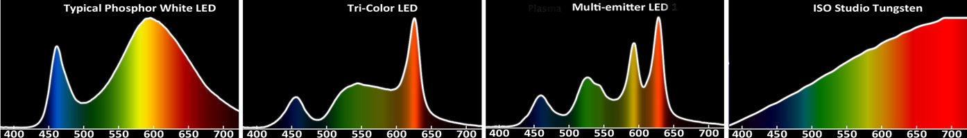
The curves shown above are the spectral power distributions for the three approaches to producing white light that we will discuss as well at that of an incandescent lighting instrument. While the discontinuous spectral distribution of Phosphor White LEDS (far left)
may appear white to the eye, and the color of objects illuminated by it appear natural to the eye, to film emulsions and digital imaging systems designed to reproduce accurate color under continuous spectrum light sources (like daylight or incandescent lamps), the
color of the same objects will appear unnatural on screen. That is, the hue of an object being illuminated by this "apparent white light" can be drastically different than expected when it appears on the screen. For example, below is a "Macbeth chart" contrasting
the resulting effect upon different color swatches of studio tungsten light and a representative Phosphor White LED lighting instrument.

Split Macbeth chart: each color patch shows the visible effects of studio tungsten light in the top half of the patch, and a representative Phosphor White LED lighting instrument in the bottom half.
A common test chart used for assessing color performance of motion picture imaging systems, the chart above would be more accurately called a "split Macbeth chart" because each color patch shows the visible effects of the two light sources – studio tungsten in the
top half of the patch, and the Phosphor White LED lighting instrument in the bottom half. Although your computer display is not likely to be a calibrated reference monitor, the wide variations in color patch hue caused by the discontinuous spectral distribution of
the Phosphor White LED lighting instrument should be readily apparent.
What accounts for these results? First, as you can see from its' spectral power distribution above, Phosphor White LEDS, compared to continuous light sources, have no output at wavelengths shorter than about 425nm, which means that violet colors don't render well.
Second, there is minimal output in the medium blue-cyan-turquoise range from about 465-510nm, which is why the aqua-type colors don't render well either. Lacking these complementary colors within the spectrum, skin tones and warm, amber-yellow colors don't stand
out. Third, with the long-wavelengths cutoff in the high-600 nm range, pinks, reds, oranges, and other long wave-length colors tend to look a little dull under Phosphor White LEDs, compared with how they look under continuous spectrum light sources (daylight, HMI,
Tungsten) which extend all the way out on the long-wavelength end. Finally, as you can see from the gray scale at the bottom, this particular Phosphor White LED Luminary has a overall magenta bias.
It is a common mistake to think that a custom camera white balance can correct for the deficiencies of LEDs. While you can white balance out/time out this magenta bias
in digital video cameras/digital film intermediate, the camera/timer is not able to replace the parts of the spectrum that are missing all together. And since gels only
rebalance the spectral distribution of a light source by passing the wavelength of the color that they are, gels cannot correct for these deficiencies either because there is not light of those wavelengths to pass in White Phosphor LEDs to begin with.

This inability of LEDs to render color is very visible in tests recently performed by The Academy of Motion Picture Arts and Sciences (AMPAS) as part of their “Solid State Lighting Project Technical Assessment” (see below for details.) In one (above) a model was photographed wearing a dress that had a number of different blue/cyan tints. Footage was shot with both a true tungsten source and a White Phosphor LED source. The tungsten-lit footage displayed all of the subtle differences in blue/cyan tones in the fabric, while the LED-lit footage, lacking cyan output, showed just a nice blue dress, without the same richness of hue. Since the light doesn’t put out much cyan, the camera/film simply can’t record it because those wavelengths are not reflected by the dress.
The same holds true of flesh tones illuminated by LED light. As is also evident in the pictures above, skin tones don’t reproduce well under LED lights because of the steep drop off of high frequency colors (above the 600nm cut off) such as pinks, reds, oranges, and other long wave-length colors. As the illustration below, comparing the reflected spectral distribution of a Caucasian skin tone under theoretical pure white light (an even distribution of all wavelengths) to that of a Phosphor White LED demonstrates, absent these wavelengths the skin tones look pale under LEDs because light reflected by the skin tone is likewise absent these critical long wavelength colors.
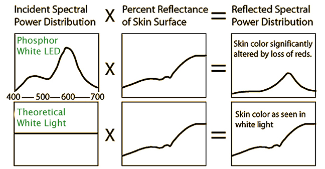
Reflected Spectral Distribution of Caucasian skin tone under theoretical White Light and Phosphor White LED Light
In the picture above illuminated by the Phosphor White LED, both the cyan/blue dress and the skin tone, don’t reproduce well because you can't get accurate color reflected from an object unless that color is in the light in the first place. In other words, if the light source doesn’t generate the color (cyan), it is not reflected by the object (the dress) and so the camera/film simply can’t record it. And, as Cinematographer Daryn Okada, ASC, discovered the hard way, color gel packs, camera white balance, or digital intermediate timing can’t bring it out if it isn’t there to begin with.
Like many of us, Daryn Okada uses LEDs as “touch up” lights to add a little something where key lights don’t cover. Needing to touch up a face on one talent mark, he once hid a small LED unit behind a chair, to add some glow to an actress’s face when she reached a mark where the keys had fallen off. “The manufacturer claimed the unit to be a ‘tungsten LED source,’” he recounts. “She stopped right in the doorway, where I had this LED, and looked fine. But when I got the dailies back, her face was totally magenta.” What’s worse, Okada says the image could not be repaired in post, because there wasn’t enough of the right color of light in the scanned negative for a color timer to bring out.
Had Daryn Okada been shooting with a digital video camera, he would have noticed the off color of the LED source immediately. But, given the limited spectral output of LEDs, his ability to remedy
the problem would have been limited. If he white balanced the camera for the LED source, the background of the room beyond the doorway that was lit by tungsten lights would turn very green. In a
mixed light situation such as this, the only alternative is to match the LED source to the prevalent tungsten source with a custom gel pack on the LED head. But, since gels rebalance the spectral
distribution of a light source by passing the wavelength of the color that they are, gels cannot correct for these deficiencies because there is not light of those wavelengths to pass in
White Phosphor LEDs to begin with. In other words, White Phosphor LEDS are so deficit in certain parts of the color spectrum that by the time you came up with a color gel pack to match them to a
continuous light source like a tungsten light, the LED panel would put out very little light with all those gels on it.
To understand why this is so, we need only look at a similar situation: the conversion of tungsten light to daylight using full CTB gel. As you can see in the Spectral
Power Distribution graph of tungsten light above, tungsten light is so deficient in the blue part of the spectrum that it takes a quite saturated blue gel to balance it
to daylight (see spectral transmission of Full CTB gel below). In fact, the transmission coefficient of some Full CTB gels is only 24%, which means that it passes only
24% of the source. That is why gelling tungsten lights
is a very inefficient way of creating a daylight source (a tungsten 1000w gelled with CTB becomes a 240W daylight source.)
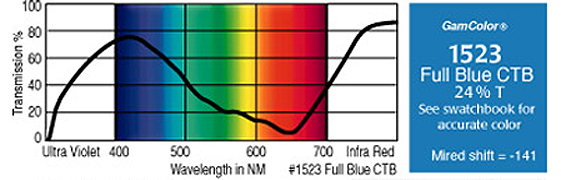
Spectral transmission of Full CTB gel
A gel pack that would match a White Phosphor LED to tungsten light would have to include violet to extend its’ spectral output below 425nm. It would have to include medium blue, cyan, and turquoise to fill in the missing wavelength from 465-510nm. Finally it would have to include pink, red, and orange to extend its’ spectral output beyond its’ 600nm cut-off. All of these gels would have to be quite saturated, since there is very little, if any, output of these wavelengths in White Phosphor LEDs to begin with. Imagine how much light you will get out of a LED light panel with such a gel pack (LED light panels put out barely enough to begin with, and have no output to waste to such accurate color correction.) Since, under most circumstances it is simply not feasible to completely match LED sources to tungsten sources with a gel pack, in mixed light situations such as these you are left, without recourse, with the off color generated by LEDs.
If the actress in Daryn Okada’s shot were the model in the blue/cyan dress above, you can imagine what would happen when she stepped onto the mark lit only with the LED source by looking closely at the contrasting
photos above. Since, under the circumstances, Daryn Okada could not white balance for the LED source (and it would not be feasible to match the LED source with a gel pack) the rich blue/cyan hue of her dress in
the left photo would turn into the simple blue of the right photo. The vibrant skin tone of the left photo would turn into the flat skin tone of the right photo, and it would have an overall magenta cast to boot.
This example clearly demonstrates that White Phosphor LEDs, simply by nature of their discontinuous spectral distribution, cannot accurately reproduce colors on screen under all circumstances no matter how tightly their bin parameters are set.
While they are less than perfect at reproducing parts of the color spectrum, the color rendering of Phosphor White LEDs may be adequate in certain situations. For a specific application, say where lights must be
operated off of batteries, a LED fixture offers the unique advantage of greater power efficiency over conventional lights, which may out weigh its shortcomings in color rendering.
After all the color spectrum of LEDs is not horrendous. For example if you were to look at the image of the model in the cyan/blue dress lit by Phosphor White LEDs above, you wouldn’t say it looked bad. But, when viewed side-by-side with the same
image lit by a continuous tungsten source, you see what it should have looked like. For that reason whenever color rendition is critical I always opt for a continuous spectrum light source - especially shooting interviews where rendering a realistic
flesh-tone is critical.

For example when I lit Ted Kennedy in his old age, and it was important to convey the impression of a robust and healthy elder statesmen, I fought hard to use a more expensive HMI interview kit
consisting of Joker HMIs with Chimera Light Banks, when the show producers wanted me to use a cheaper LED kit. To convince the Producers that there would be a significant difference, I brought the
LED kit. After seeing the difference they came up with the extra money for the HMI kit because it was important to render a healthy flesh tone.
 
The table top on the left was illuminated by a high color rendering source,
while the one on the left was lit by a low color rendering source
I also wouldn’t try to light a table-top food/product shot with LEDs either. As is readily apparent in the shots above, because of their limited color rendering capability, food presentation that will look vibrant and colorful to eye, under LEDs will tend to look a little dull on camera.
By comparison a full spectrum daylight source such as HMI or LEP will capture the vibrant colors. Likewise, I wouldn’t try to mix LEDs with a uniform continuous light source, such as a studio lit with tungsten fixtures. If caught in isolation,
their color deficiencies will be quite noticeable and unacceptable in comparison to the tungsten. And, I would always choose a discontinuous source like high CRI fluorescent tubes over LEDs because the discontinuous color spectrum of Kino Flos can be
easily corrected with gels - where LEDs can not.
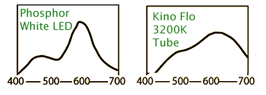
Once the green spike of
Kino-Flo’s True Match tubes have been corrected by the application of minus green (magenta) gels, the resulting spectral distribution is nearly continuous and contains a greater proportion of the long wave length colors that
are so critical to rendering flesh-tones accurately (see illustration above.)
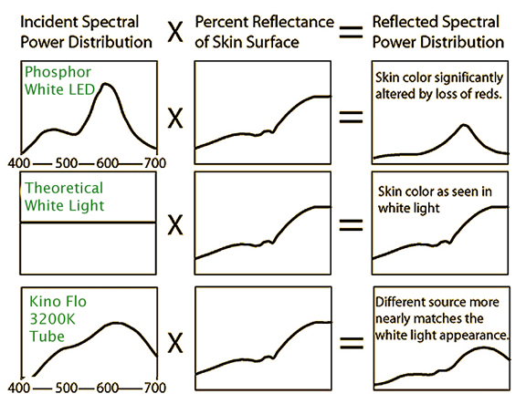
Where skin-tones are significantly altered by the steep drop-off of long wavelength colors in LED light sources, Kino-Flo’s high CRI True-Match tubes contain sufficient light in that critical part of the spectrum to render
skin-tones realistically (see illustration above.) In other words, once Kino Flo True Match Tubes have been corrected for their green spike, they provide a nearly full spectrum source. With LEDs, it is nearly impossible to correct for their
deficiencies with gels. Unfortunately, the limitations inherent in remote phosphor technology make it unlikely that we will ever see a Phosphor White LED with as continuous a color spectrum as the best Flos do today. Where this is contary to the popularly held belief that improvements in
LED technology will result in better and cheaper fixtures, allow me to explain in some detail.
A close look at the improvement in lumens per watt efficiency of LEDs reveals that it, in fact, comes at the expense of color rendering. For example, the improvement in the Cree Xlamps from the original MT-G to the new MT-G2 demonstrates this clearly. According to
Cree’s website the MT-G2 “pushes performance limits to redefine lumen levels and efficacy (it is 25% brighter then the MT-G).” But when you compare the spectral output of the two Cree Xlamp emitters side by side you see that the greater lumen output of the MT-G2 comes
at the expense of color rendering capability. The reason for this is that there are limitations inherent in the remote phosphor technology that the Cree XLamps use. And, regardless of blind optimism, these limitations make it unlikely that we will ever see a Phosphor
White LED with as continuous a color spectrum as we get from Kino Flos today.
As you may recall, in the remote phosphor approach to white light, the Cree designers manipulate the color spectrum put out by a blue InGaN LED to a desired "white light" by applying phosphor layers of distinct colors that are activated by the LED’s “Pump” color
(450nm in the case of blue InGaN LEDs) to extend the color spectrum by a process called a “Stokes Shift.” Depending on the chemistry of the phosphors used, the color balance of light generated by remote phosphor technology can approximate daylight, or be stretched
to approximate 3200k tungsten color balance. The “5500K” white LEDs use semi-transparent phosphors so the blue "pump" color comes through. In contrast to 5500K LEDs, the warmer “3200K” white LEDs have to use more phosphors and so are more opaque to the pump color,
and are therefore much lower in efficiency.
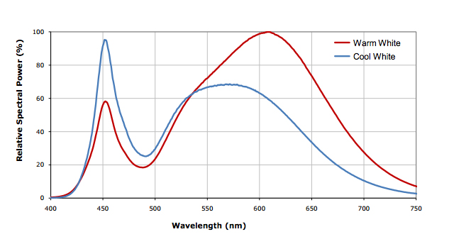
Spectral output of the Cree XLamp MT-G easyWhite LED
This tradeoff in lumen output is clearly evident if you compare the spectral output of the older Cree XLamp MT-G to the newer MT-G2. As you can see by their spectral distribution graphs above and below, the 25% greater output of the newer MT-G2 is at the
expense of longer wavelength colors. The high frequency cut-off in the Cree MT-G comes at about 615nm. In order to gain more lumens, Cree dopes the MT-G2 less heavily (so that more light from the emitter comes through) and as a result the high frequency
cut-off comes sooner at 600nm and the long wavelength colors of the MT-G2 drop off much quicker than in the MT-G. Since, it is the long wavelength colors that make flesh-tones “vibrant,” the additional output of the MT-G2 comes at the expense of flatter,
paler flesh-tones. And, the more appreciable drop-off of longer color wavelengths in the MT-G2 results in pinks, reds, oranges, and other long wavelength colors looking duller as well. Given the unavoidable energy loss in the Stokes shift process demonstrated
in the “improvement” in the Cree Xlamps, it is doubtful we will ever see a significant improvement in the color rendering capability of Phosphor White LEDs.

Spectral output of the "improved" Cree XLamp MT-G2 easyWhite LED
For this myriad of reasons, the remote phosphor approach to generating photographic white light
with LEDs has been all but abandoned by the more serious manufacturers of LED luminaries for motion picture production – leaving only manufacturers of LEDs for the general illumination market and those manufacturers that repurpose them for motion picture lighting applications.
No matter how much effort is spent on optimizing Phosphor White LEDS to higher light output and higher CRI ratings for the general illumination market, without a mass market for continuous spectrum remote phosphor LEDs (as opposed to high CRI – they are very different)
tuned to our specific needs, there is not much hope of seeing a true “Tungsten” LED. In other words, because our requirements do not coincide with those of the mass general illumination market, LED manufacturers - outside of possibly Osram (see below for details) - are
not developing Phosphor White LEDs specifically for motion picture lighting – it is simply too small a market in the larger scheme of things. As long as that is the case, there will be higher CRI LEDs developed but we won’t see a meaningful attempt to address the color
rendering deficiencies of Phosphor White LEDs for photographic purposes.
The OSRAM KREIOS LED chip
Since, the color spectrum of LEDs can be manipulated by blending phosphor layers, it is possible to tune their output specifically for the color sensitivity of film emulsions and digital imaging systems. The motion picture lighting division of OSRAM did just this
in the KREIOS LED stage light module that Mole-Richardson uses in their MoleLED 12 Pack.

The OSRAM Kreios stage light LED module
The KREIOS stage light module (pictured above) is a metal core circuit board with 20 high-output blue LEDs each topped with a remote phosphor dome. The phosphor domes are an OSRAM proprietary design, which are blue light activated to produce light that is a very
close approximation of Tungsten and Daylight. While, remote phosphor technology is commonly used to extend short wavelengths to create a fuller color spectrum in Phosphor White LEDs, OSRAM was the first LED manufacturer that set out to use remote phosphor technology to
match the spectral sensitivity of Tungsten and Daylight balanced film stocks.
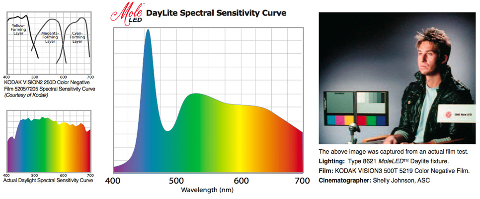
The spectrum distribution of the Daylight balanced MoleLED clearly shows the blue light emitted by the InGaN-based LED
(peak at about 465 nm)
as well as the more broadband light created by phosphors.
And, with the help of Kodak, Panavision, Technicolor, and Shelly Johnson ASC, multiple film tests were shot with the KREIOS stage light module in order to verify the color generated by the MoleLED on set would translate to the color viewed in film dailies.
This attention to detail and strict testing has resulted in a LED fixture that almost seamlessly mixes with existing Tungsten Halogen light sources, natural daylight, or any daylight balanced light source.

The spectrum distribution of the Tungsten balanced MoleLED clearly shows the blue light emitted by the InGaN-based LED
(peak at about 465 nm)
as well as the more broadband light created by phosphors.
Even though OSRAM was successful in using remote phosphor technology to closely match the spectral sensitivity curves of Tungsten and Daylight balanced film stocks, this approach has several drawbacks. Since the OSRAM KREIOS stage light module is specifically
designed for motion picture lighting applications, and not mass produced like Phosphor White LEDS, they are considerably more expensive – making the MoleLED 12 Pack (pictured below) one of the more expensive LED light panels on the market.

The MoleLED 12Pack
And, given the seemingly unavoidable energy loss in the Stokes shift, the remote phosphor approach is not the most efficient method to achieving white light with LEDS. And, finally, the consistency of the color output of remote phosphor LEDs is
effected by the binning and manufacturing tolerance of their blue pump (generally optimized between 450nm and 460nm), thermal management in the fixture, the ageing of the phosphors, and even the ambient temperature.
For example, a one degree shift in the junction temperature of the blue InGaN LED (pump color) in remote phosphor LEDs, will cause a +/- 2nm shift in the dominant wavelength. If compounded by the average wavelength variation of +/- 2nm of blue InGaN LEDs, a 5nm divergence from the prescribed 455nm wavelength of the pump color will create color inconsistency of 5 MacAdams ellispses. While not readily apparent to the eye, image capture systems will easily see this variation.
However, much effort is being spent on optimizing these devices to higher light output and higher
operation temperatures. With development ongoing, the efficiency of phosphor based LEDs is sure to rise, but without a mass market for remote phosphor LEDs tuned to our specific needs, there is not much hope of the prices coming down significantly.
Since, market competition often focuses on brightness (lumens/watt), some manufacturers opt for brighter LEDs with unappealing color characteristics, while others select LED chips with better color characteristics and rely on good optical design and drive electronics
to produce reasonably good output. With all these factors in play, it would be quite misleading to judge the quality of an LED fixture strictly on the basis of brightness. Manufacturers using remote phosphor technology are forced to balance these competing priorities, and each approaches it in
their own way.
Tunable Multi-emitters
A more efficient approach to generating white light with LEDS, and one resulting in more lumens/watt, is to use tunable multi-emitters. These lights use multiple LEDs that each emitt light at different wavelengths. The simplest form of a multi-emitter instrument is a
"tri-color panel" using red, green and blue LEDs, also known as an RGB LED. While the RGB approach is capable of delivering not only a vast array of colors as well as tunable white light, the CRI (Color Rendering Index) is quite low. The typical color rendering
achievable for such a system ranges between 40 and 60 depending on the targeted color temperature (3200K or 5500K.) Motion picture lighting typically requires a CRI in excess of 80, and higher the value the better. Therefore, an RGB tunable emitter may be
well suited to color washing applications in stage lighting, it is less suitable for creating white light for motion picture lighting applications.
A variation of the multi-emitter technique that is better suited to motion picture lighting uses "cool white" and "warm white" LEDs within the same fixture, and provides a control to mix the colors as needed. The idea is that by mixing the two sets of LEDs, the user achieves a
nominally correct CCT for any color temperature from tungsten to daylight. While this is an intuitive solution to color balancing that one would think eliminates the need for fractional CTO and CTB color correction gels to achieve an intermediate color
balance, this approach does entail a compromise non-the-less.

If on the chromaticity diagram above, you were to plot the color point of two illuminants, all the colors that are possible by mixing the two colors of light will be located on the straight red line drawn between the two points. However, the line (black line above)
that would be charted by heating a black body radiator (as it turns red, orange, yellow, white, and finally blue as it is heated) is not a straight line, so it is not possible to create light that remains neutral in terms of their green/magenta shift, while mixing
only two colors. And, since neither the "cool white", nor the "warm white" LEDs in bi-color fixtures emit frequencies above their 625nm cut-off, blending them is not going to correct their deficiency of long wavelength colors, nor improve their generally poor rendition of flesh-tones.
This fact is readily apparent in the spectral distribution graph for the EPISTAR HV LED below. A high CRI (>90 at CCT 2700 k – 3000 k) LED fixture that mixes two red and two blue emitters in the same dome, the EPISTAR HV's output drops off appreciably at 640nm.
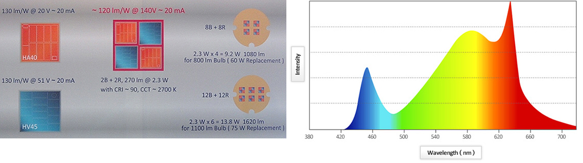
Red/Blue LED emitter configuration of the EPISTAR HV LED (left.) Spectral Output of the EPISTAR HV LED (Right.)
Another variation of the multi-emitter technique that is even better suited to motion picture lighting uses additional LEDs that emit additional wavelengths to create a closer match to natural daylight or studio tungsten light. For instance, the addition of an
amber and green emitter (creating an RGBA system) significantly enhances the CRI of the light generated while still maintaining the desired color point. The primary advantage to RGBA systems is that color flexibility is still achievable, but more importantly for motion
picture lighting applications, it is possible to walk the white point along the black body line while still maintaining a CRI approaching 90.

RGBA emitters do however present LED lighting manufacturers with some design challenges. Delivering a consistent color across the beam without color fringing or shadowing can be a complicated task. Reducing the optical source size of the LED or LED system can
improve the color mixing. One approach is to create a multichip LED (like the one pictured above), locating the individual colors as close as possible and therefore reducing the mixing distance. Although various multi-chip packages exist, few exist that enable
both high flux density (output) and color mixing. Most multi-chip packages are limited to a low drive current, reducing the flux density and output. Alternatively one may use multiple discrete high output sources, but this increases both the optical source size
and color mixing challenge. Such fixtures typically place a diffusion material immediately over the LEDs to help blend the discrete colors, but this comes at a loss of output.
Another problem is that, while it is relatively easy to put a dimmer on an LED, and blend two different color LED chips to achieve variable color mixing, as we saw above it is quite a different matter to track the color so that it remains on the black body locus
at every point from daylight balance to tungsten balance. Maintaining a specific color temperature at a high CRI while dimming is made even more difficult by virtue of the fact that temperature in the LED changes when they are dimmed. Change in temperature shifts
output wavelength as well as efficiency, and different LED chips change efficiency at different rates and at different temperatures. For these reasons, a more complex approach to dimming is required in order to control all these factors.
Some manufacturers start by incorporating more colors of LED chips into the fixture in order to counter the shift in green/magenta bias as the color tracks along the black body locus. The chips are controlled by microprocessors using algorithms to continuously
regulate the intensities of the different colored LEDs so that the mixed light gives the desired color temperature at any dimmer setting. Using multiple LED colors within a white-light fixture increases the total color space achievable by the light, and in
this way greatly improves on the limited color rendering of Phosphor White LEDs when used alone. Using this approach also allows the manufacturers to calibrate each fixture at the factory to compensate for any difference in the color output of the particular
LEDs. Without a doubt, multi-emitter LED fixtures require a complex set of design considerations to deliver consistent color. These fixtures require intelligent drivers that can ensure Color and CRI consistency over time and temperature through predictive means.
The better multi-emitter designs, like the new Arri L7 LED Fresnels (see below for more details) incorporate a color-feedback system of self-monitoring sensors to ensure stable color across a range of output levels, as well as correcting changes in performance
caused by ambient temperature and component aging, which ensures consistent color temperature. These units use an LED array optimized for film and video image capture, with standard color temperature presets. These arrays can create broad-spectrum white light
and, unlike conventional multi-emitter LED lights, the color temperature remains consistent throughout the full range of dimming, ambient temperature and life of the unit. The drawbacks to this approach are that they are expensive (they require micro-processers)
and their spectral distribution is still discontinuous. Even though they emit additional wavelengths to create a closer match to, say, tungsten lighting, as we can see by their spectral power distribution graph below, the resultant curve is very "spikey". This
has the same noticeable side effects in color reproduction as discussed above. Like remote phosphor LEDs, tunable multi-emitter designs, simply by the nature of their discontinuous spectral distribution still cannot reproduce colors on screen with complete accuracy.
Unfortunately it is very hard to judge with your eye how an LEDs spectrum is going to line up with the sensors in the camera. As we have seen, eye response and camera response can be quite different. Additionally common color meters, like the Minolta III F, are
completely useless with LEDs. The meter makes its calculation of the color temperature based on an assumption that the light source has a continuous spectrum. Color readings of an LED have been shown to be misleading for both correlated color temperature and
green/magenta shift. To make matters worse the CRI ratings published by manufacturers are useless if not downright misleading.
CRI and Color Rendering
Contrary to popular belief, CRI ratings are not a valid measure of judging the color rendering capability of LED luminaries for photographic purposes. First, the CRI Index was not designed for photographic purposes, but simply to provide a reference scale for general
illumination. It is as follows:
- CRI 90 - 100: Retail (merchandise, artwork) and work spaces (design) where faithful color rendering is critical.
- CRI 70 - 90: Most office, retail, school, educational, medical, and other work and residential spaces where good color rendering is required.
- CRI as low as 50: Industrial security and storage lighting where color fidelity is not important.
As you can see the CRI index makes no mention of photographic reproduction. It is simply because there is no means by which to measure for photographic purposes the discontinuous output of LED lights (CCT is for continuous spectrum black body radiators only) that LED
manufacturers use the CRI index.

Second, the CRI index is a measure of the ability of a light source to reproduce a minimum of 8 mid saturated colors faithfully (a different 8 colors are used in Europe.) As such CRI ratings are at best a very limited measure of the color rendering capability of a
light source. And, finally, it is possible for a LED luminary manufacturer to game the system by tuning the output of their LED to the limited color range of the CRI color scale and achieve a high CRI rating while delivering mediocre results on screen. Let’s take up
hese issues one at a time.
What makes CRI an imperfect measure for photographic purposes? It really only tells you how a light source will perform in a narrow band of mid saturated colors, and it is best with sources that lie near to the line of a black body radiator on the Chromaticity diagram and don’t have too high or too low a color temperature. Because CRI wasn’t designed as a measure for “White Light” produced in the way that an LED produces it, it can produce misleading results when applied to LEDs. With a large gap in wavelengths from 465-510nm Phosphor White LEDs
can do a bad job of rendering cyan but still get a respectable CRI because the eight indices for the individual test colors are averaged together to produce the final CRI. In other words, a light source such as LEDs can score well even though they render one or
two colors poorly because the CRI average hides the deficiency.
Additionally, because the eight standard sample colors are all of fairly low saturation, the CRI tells you nothing about how a light source will perform when rendering deeply saturated colors. For instance, saturated colors that fall between the widely separated peaks
of the spectra of Phosphor White LEDs will perform poorly, but the CRI scale won't register that deficiency either.
Finally, it is possible for a LED luminary manufacturer to game the system by tuning the output of their LED to the limited color range of the CRI color scale and achieve a high CRI rating while delivering generally poor results on screen. Since the eight standard
sample colors do not include an orange or red, CRI ratings will not tell you how a light source is at rendering these long wavelength colors that are so critical to rendering an accurate Caucasian flesh-tone. In other words, since it does not measure above the 600nm
cut-off of Phosphor White LEDs, CRI does not tell you how LEDs are at rendering flesh-tones.
These inherent problems with using CRI to measure the color rendering capability of solid state lighting are becoming widely recognized and a new metric, CQs or Color Quality scale, is under development by the national Institute of standards and technology (nIst) to address these and other concerns. Until then, the CRI ratings of manufacturers should be taken with a grain of salt.
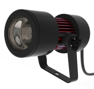
The "Tru Color" Foton 33W Single Emitter LED Light
For example, PRG has introduced a White Phosphor LED, the Foton, that boasts a CRI rating greater than 97. In typical marketing hyperbole, PRG claims on their website that “Producing a 97+ CRI … the Foton is the most color accurate digital light source designed specifically for motion picture, broadcast and professional photography.” Given the high CRI indices the Foton is able to achieve on the eight standard CRI colors (see illustration below), that is probably true.

But, if we look instead at the Spectral Power Distribution graph of the Foton (below), we see that the long wavelength colors that are critical to rendering a realistic flesh-tone still drop-off appreciably. Even though the Foton suffers the same inherent limitations of all Phosphor White LEDs to generate colors with long wavelengths, this deficiency is not reflected in its CRI of 97+ because these long wavelength colors are not part of the narrow range of CRI colors. Since the rendering of a realistic flesh-tone is paramount in cinematography (whether for film or Digital), CRI is simply not a valid measure of a LED’s color rendering capability for motion picture lighting.

For these reasons, the best approach to judging the color of a LED luminary is to shoot tests. A side-by-side comparison using a color chip chart and a full spectrum light source, will clearly demonstrate how the camera system will respond to a specific LED
fixture. To see such camera tests of wardrobe, set, and make-up for the different approaches to achieving white light with LEDs that we have discussed, use this link to the
Solid State Lighting Project Technical Assessment generated by the Academy of Motion Picture Arts and Sciences.
LEDs, Color Meters, and Color Correction Gels:
Its not that LEDs can not be read by color meters (Konica Minolta manufactures a color meter, the 200A, that will accurately place LEDs in color space), rather it is the case that color meters, even
the 200A, cannot generate color readings that are useful for photographic color correction purposes because there does not exist a series of corrective gels calibrated for the discontinuous and varied
spectral output of LEDs as there is for continuous spectrum sources like Tungsten lights. This creates the problem that, in contrast to HMIs and Tungsten lights, where you know what to expect
using, say CTO gels on these lights, the use of CTOs on LEDs have unintended and undesirable consequences that you are probably unfamiliar with. Here’s why:
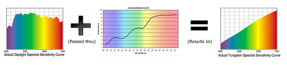
3/4 CTO gel passes only certain wavelengths (represented by the spectral transmission curve (center)) of daylight (left)
to create the color spectrum approximating that of a 3200K tungsten light (right.)
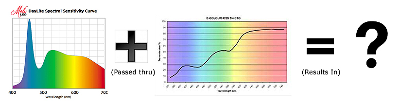
The same 3/4 CTO gel applied to a daylight LED (left) passes the same wavelengths (represented by the spectral transmission curve (center))
to create an unknown color spectrum that does not approximate a 3200K tungsten light.
What makes it even possible for specifically formulated color sheets to be used to create a desired effect is that with a continuous light source you can carve any spectral distribution you want out of
it by tinting gelatin to selectively pass only certain wavelengths because it is continuous. To use an anaology, it’s like baking cookies. To make cookies you start with dough that is rolled out
in a uniform sheet so that your gingerbread man cookie cutter will cut out a whole man. If your dough sheet is not uniform, but irregular or full of holes, when you use your gingerbread man cookie
cutter, you come up with a man missing appendages or possibly his head. The same is true of using CC or LB gels on the discontinuous spectrum of LEDs, when you apply the “cookie cutter” of, say
3/4 CTO, to a Phospher White Daylight LED, you cannot be certain what you will come up with (see illustration above) What is certain is that it won’t resemble what you wanted.

HMI lamps offer a nearly continuous spectral output that closely approximates
that of mid-day sunlight (the superimposed white trace.)
A good example of this is what happens when you try to convert a 5500K LED to 2900K with Full CTO as DP Michael Morian recently did in some camera tests .
Where you can do it with HMIs because there are long wavelengths in it’s nearly continuous spectrum (see above), since LEDs don’t put out much beyond 625nm, Mike found that there is not much for a filter to pass to rebalance the light output to 3200K. As you can see from the results of his test reprinted below, the “corrected light” comes out too cool in comparison to a Tungsten source.

The light output of a tungsten light (left) compared to the output of a Litepanels 1x1 Daylight Super Spot LED light (right) "corrected" with Full CTO Gel

Left: Tungsten lit scene with Lee 147 Apricot gel on backlights and no gel on side lights.
Right: Daylight LED lit scene with Lee 147 Apricot on backlights and sidelights corrected to 3200K with Lee 204 Full CTO. Note greenish cast to corrected LEDs.
But, that is not all. Another unwanted consequence comes from the fact that Full CTO is designed to pass extra green (as you can see below there is a bump in the spectral transmission curve of Full
CTO in the green portion of the spectrum) and so it creates, given the amount of green inherent in the Litepanels 1x1 Daylight Super Spot LED to begin with, a disproportionate amount of green (creating an overall green bias)
to the “corrected” light (see test result above.) The same would be true when used on Phosphor White LEDs in general.

As indicated by the its' spectral transmission curve, Full CTO passes
a disproportionate amount of the green portion of the spectrum.
The gel pack that eventually made the Lightpanel 1x1 Daylight Spot marginally similar to a tungsten light (see test results below), was only able to do so at the expense of two stops. In other words, it reduced the lights output to 25% of what it started out at (so much for the greater efficiency of LEDs.)

The light output of a tungsten light (left) compared to the output of a Litepanels 1x1 Daylight Spot LED light (right) "corrected" with a gel pack
that reduces it's output by two stops
That we get unexpected and undesirable results applying standard Color Correction gels to LEDs highlights an important fact about color meters. It's not that LEDs can not be read by color meters (the Konica Minolta 200A will accurately place LEDs in color space), rather it is the case that color meters (even the 200A), cannot generate color readings that are useful for photographic color correction purposes because there does not exist a series of corrective gels calibrated for the discontinuous and varied spectral output of LEDs as there is for continuous spectrum sources like HMIs and Tungsten lights.
 
The Konica Minolta 200A Color Meter can accurately place LED light sources in color space
using Correlated Color Temperature (CCT) and delta UV coordinates.
By definition, a photographic color meter is “a meter used to select the appropriate filters, with the sensitivity adjusted to match that of the film or digital camera sensor” (page 2 of
the Konica Minolta Product pdf for the 200A .)
In other words, to be useful in photography, a color meter must measure the color of light and present the data in terms that a photographer can use. As you may recall, you set the earlier Minolta
Color Meters (the II and III) for the type of film being used (Type A, B, or D) and it generated readings in Kelvin and CC (Color Compensating) and LB (Light Balancing) scales, and provided on the
back an index that directly correlated the reading to corrective gels. While the Correlated Color Temperature (CCT) readings with delta &uv specifications generated by the 200A will accurately place a light
source (including LEDs) in color space, the readings do not translate to CC (green/magenta) or LB (red/blue) measurements that are meaningful (see table below.)

The correlation between CC (Color Compensating) values and Color Correction Gel
To be used for photographic corrective measurements, the 200A would have to offer corrective measurements to compensate for the absence of wavelengths below 425nm, the drop out of wavelengths between
465-510nm, and the steep drop-off of wavelengths over 600nm in the output of the typical Phosphor White LED panel. But, it can’t do so because there are no calibrated gels (like the Wratten Filters,
CTOs, CTBs, Plus/Minus Greens designed to be used with the Minolta Color Meters (the II and III) to correct continuous light sources) available for this purpose. In short, for a color meter to work
requires complementary imaging systems, light sources, and corrective gels calibrated for both. To use the available color correction
gels (listed above) to correct LEDs is a misapplication of a finely calibrated system of correction designed for continuous spectrum light sources only and, as Michael Morian's test results clearly
demonstrate, yields unexpected and undesirable results
when applied to LEDs.
Someday, Rosco, Lee, or Gam, will come up with gels calibrated for LEDs, but I don't think it will be any time soon given that, as the Academy of Motion Picture Arts and Sciences (AMPAS) tests
demonstrate, there is no standard spectral output for LEDs. Perhaps, after LED technology has become standardized, a system of calibrated gels will be created. But until then, color meter readings
(even those generated by 200A) are not a suitable means of color correcting LED luminaries for photographic purposes. While tungsten lights are hot, bulky, and draw a lot of power by comparison, the
one thing that can be said of them is that they can be measured and you can apply a color correction gel specifically designed for its' spectral output to achieve desired results. In other words, you
know what the results will be and won't have to give some post pro a bagful of money to straighten out what the LED screwed up.
Lumen Maintenance/Depreciation
How well a lamp maintains its lumen output over time is referred to as lumen maintenance. Greater lumen maintenance means a lamp will remain brighter longer. The opposite of lumen maintenance is lumen depreciation, which represents the reduction of lumen output
over time.
A number of factors effect lumen maintenance/depreciation. In the case of discharge lamps (HID or HMI) and incandescent lamps (Tungsten), the repeated cycles of heating and cooling that their quartz envelope goes through, cause the molecules to lose their
crystalline structure. As a result, the quartz envelope over time loses some of its transparency and becomes more opaque. This process is called devitrification. As the quartz envelope devitrifies, it blocks more of the light and prevents it from escaping
from the envelope, contributing to the depreciation of the lumen output. Another cause of lumen depreciation in discharge lamps (HID or HMI) and incandescent lamps (Tungsten), is that metal from their filament or electrodes evaporates and condenses on the
inner wall of the quartz envelope, causing blackening. This also contributes to the loss of light output.
A third factor that effects lumen depreciation is the intended use which is reflected in the bulb design. One way to think about HMI lamps is as a metal halide type lamp with a rock-n-roll life philosophy of "live fast, die young." To increase output, improve
luminous efficacy, and color rendering, HMI lamps are designed with comparatively very short electrode gaps. However, their increased luminous efficacy places an increased load on the bulb wall which accelerates the devitrification of their quartz envelope;
which, in turn, leads to increased lumen depreciation. In other words, their brilliance comes at the expense of lamp life. Over their relatively short life of 500-750 hrs, it is not uncommon for HMI lamps to lose 15-20 percent of their initial lumen output
before they fail all together.
Evaluating the lumen maintenance of an LED luminary is more complex because in many ways it is more complex than traditional fixtures. An LED is an electromechanical system: in addition to the essential light emitting source, an LED luminary also includes a
provision for heat transfer, electrical control, optical conditioning, mechanical support, and protection, as well as aesthetic design elements. Because the LEDs themselves are only one part of this elaborate electromechanical system, the affect of these
other components must be taken into account when determining the lumen maintenance of an LED luminary.
For instance, while LEDS do not radiate heat like a tungsten filament, half or more of their input energy may be converted to heat in current carrying components. This heat must be conducted away from the diodes for an LED to operate efficiently. This situation
requires a heat conducting assembly, be it a passive heat sink or active fan cooling, that will operate reliably over an extended period of time - most do not. For proper operation, the power supply and electronics of an LED luminary must provide a well-controlled
DC drive current and other control features - most begin to fail long before the rated life of the product.
Any optical components must also be able to withstand years of exposure to intense light and possibly heat without yellowing, cracking, or other significant degradation. Reflecting materials need to stay in place and maintain their optical efficiencies. Since
it is nearly impossible, even in the best designed LED luminaries, to completely protect against system degeneration of the type described above, the lumen maintenance of an LED luminary is significantly less than that given by manufacturers for a single diode.
For example, recent tests from the Caliper program (US Dept. of Energy) suggest that the lumen output of many LED luminaries depreciate to less than 50% after only 500hrs (see page 27 of the summary for examples of
lumen depreciation after about 500 hours
.) While, this might not be representative of every product, the vast majority of those that were tested fell far short of the manufacturers claims of lumen maintenance.
Color Shift
In addition to losing light output, an aging luminary, also exhibits color shift. With HMI bulbs, color temperature varies significantly with lamp age. A new bulb generally will output at a color temperature close to 15,000 K during its first few hours. After
this short burn-in period, the color temperature reaches its prescribed value of around 5600 K or 6000 K. With age, however, its' arc length becomes larger as more of the electrodes burn away. Greater voltage is required to sustain the arc, and as voltage
increases, color temperature decreases proportionately at a rate of approximately 0.5 -1 Kelvin for every hour it burns. Which means that by the time it fails, after approximately 750 hours of use, its' color temperature will be between 5250 and 4875K.
Determining the color shift of LED luminaries is also complicated. That is because color stability is not exclusively determined by the performance of the LED diode. Other factors that contribute to color shift
in LEDs include LED design, materials, manufacturing processes, optics applied to the LED, and the temperature and time the LED operates. The increase in junction temperatures typical of LEDs over time can cause color shifts as noted above.
Likewise, optical
components in the LED luminary may discolor, crack, or significantly degrade after extended exposure to the intense light the luminary generates. Environmental conditions (including air quality) may cause materials in optical components to deteriorate. Finally,
luminary design my create non-uniform color characteristics such as halos or yellowish, bluish, or greenish hues around the edges of the beam, and these color characteristics may vary over time for the reasons mentioned above.
A new technology also requires a new method of measuring shifts in color. Since LEDs are not "black body" radiators (that turn red, orange, yellow, white, and finally blue as they are heated), the Correlated Color Temperature (CCT) ratings in Kelvin are not
adequate to describe color shifts in LED luminaries over time as it is in conventional lamps. This is another reason why the LED industry uses, instead, the "MacAdam ellipses" discussed earlier.
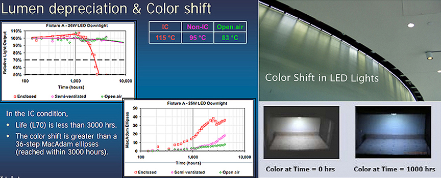
That samples in the Caliper study cited above (one is illustrated above) exhibited color shifts greater than a 36-step MacAdams ellipses and a 30 percent drop in lumens within 3000 hours, suggests that that LED luminary reached it's usefulness to serve even
as a set practical for motion picture lighting long before 3000hrs (remember one MacAdams step is not visible, two to four steps is barely visible, 5 or more is readily noticeable.) Unfortunately, the manufacturers of LED luminaries for motion picture lighting
purposes do not publish specifications for color shift over time; probably because, as the results of the Caliper study cited above suggests, they are significant and would appreciably shorten their claim of 50'000 hours of "lamp life." The better LED luminaries
for motion picture lighting applications (the Arri L7 and Gekko Kezia) compensate for color shift with active microprocessor controlled color management that involves self testing using internal color sensors (see below for more details.) However, sensors and
controls may themselves shift over time and affect color - so even such methods of color management are not full proof.
Lamp Life
In light of what we now know about LEDs, claims of 50'000 hr lamp life made by manufacturers like Litepanels should be taken as the marketing hyperbole that they are. Determining the "life" of an LED luminary is a very complex matter and how to do so is still
being hotly debated within government and industry regulatory bodies. Until a standard measure of LED lamp life is settled upon, extravagant claims of 50'000 hrs should be taken with a grain of salt.
For conventional lamps (HID, HMI, Incandescent, Fluorescent), the method for determining "rated average lamp life" is well established and easy to calculate: it is simply the point at which half the lamps cease to emit light. For LED luminaries it gets quite a bit
more complicated for several reasons. One complicating factor is that LED luminaries are made up of multiple components and usually have no replacement parts. That means, even though the individual LEDs in a luminary may be rated to last for 50'000 hours, its'
actual life will fall well short of that mark if one of its other key components fails sooner. For example, HMI ballasts are manufactured to outlast their lamps many times over, because those lamps are relatively short lived and easily replaced. But at this
relatively early stage in the development of LED technology, there's very little data available to confirm that LED drivers will last as long as the expected life of a LED diode that carries a 50'000 hr rating.
Another complicating factor is that LEDs have no filament or electrodes to burn out and thus generally keep on producing light, although at declining levels and a gradual shift in color. And, since a well designed LED luminary has a comparatively very long-rated life
(as conventionally defined), over which its' lumen output drops continuously, it also has an appreciatively greater lumen depreciation over that life than does an HMI lamp. To extend the analogy used above, if HMI lamps are "Live Fast, Die Young" Rock-n-Rollers, LED
Luminaries would be suburban Dads working 9-5 jobs. With their best years behind them and a few more pounds around their waist, they now spend their weekends driving the kids to soccer practice in a minivan, and usually fall asleep by 10pm on a Saturday night watching
TV. Given their continuous
lumen depreciation and color shift over time, it is clear that there comes a time when, like a suburban Dad, a motion picture lighting LED luminary has surpassed it working life and should be retired. Since it won't burn out in its' prime, like an HMI lamp, how
do we determine when a light has surpassed its' useable life. Clearly, this new technology requires a new approach to determining useable "lamp life" than that used for conventional lamps like HMIs.
For instance, how useful is a manufacturer's "rated average lamp life" of 50'000 hours when testing has found that complete LED luminaries can depreciate as much as 50% in just 500 hrs. Whatever the stated lifetime of any lighting product, it must reflect a
meaningful statistical measure of the performance of a given fixture design. Clearly, in the case of LED luminaries to be meaningful "lamp life" must include not only the median time to failure of the array of diodes under normal operating conditions, but
"failure" must also be defined as unacceptable lumen depreciation for the particular application rather than complete failure to light.
One such alternative rating system for LED Lamp Life proposed by the Department of Energy (DOE) LED Lifetime and Reliability Working Group
denotes "B" and "L" factors; where B represents the interval of time it takes for half of the diodes to "fail" (called B50), and L is the lumen performance level defining a "low-light failure". For example, the LED luminary that depreciated 50% in just 500
hrs in the Caliper study above would have a B50/L50 Lamp Life rating of 500 hrs. In other words, after 500 hrs, half of the diodes will have considered to have "failed" because their output dropped to 50 percent (low light output.) In this rating system B
represents the time interval in hours in which a percentage of diodes have failed, where L represents failure as defined by an unacceptable lumen performance as a result of lumen depreciation.
One benefit to this rating system, is that each industry can determine a "lamp life" that is meaningful to its' application. For example, a B50/L50 rating of 500hrs (a drop-off of 50 percent of the diodes (B50) to 50 percent of their original value (L50) in
500 hours) may be perfectly acceptable in warehouse illumination. In more demanding applications, like home illumination, more demanding criteria would be required in determining lamp life for it to be meaningful. Most LED manufactures for home illumination
use L70, or the point where lumen output has declined by 30 percent from initial output, to define the end of an LED's life because the average human eye can't detect decreases in light levels up to that point when the light is used intermittently. Once
lumen maintenance has depreciated below that point, we begin to perceive the LED luminary is not as bright as it was when we first bought it and so become dissatisfied with its' use for home illumination. Since an L of 70 (30 percent lumen depreciation)
would be clearly unacceptable in more critical applications, such as traffic signal illumination, an even more stringent definition of low-light failure would be chosen. Whatever level of lumen depreciation is chosen for low-light failure, to be meaningful
to it's users, it should be in line with existing lamp technologies used in that industry.
In the case of motion picture lighting, I would argue that nothing short of a B50/L85 criteria would be appropriate and meaningful, since that has been our experience with both HMI and Tungsten Lamps (as noted above the rated average life is the
interval in which 50% of lamps fail and with an average lumen depreciation of 80-85%.) If we adopt this criteria for motion picture LED lighting luminaries, the rated lamp life in hours would be the interval in which a drop-off of 50 percent
of the diodes (B50) to 85 percent of their original value (L85) occurs. Without a doubt, this is a more meaningful criteria by which to judge the lamp life of an LED array for motion picture lighting applications.
Unfortunately, motion picture lighting manufacturers have not adopted this rating system - possibly because it would expose their exaggerated claims of 50'000 hrs as nothing more than marketing hyperbole. Short of hard data, how can we estimate
the useable life of an LED light-panel? One way would be to apply a B50/L85 criteria to the Caliper test results for similar style architectural LED luminaries - after all their diodes are cut from the same semi-conductor wafer and arrayed in similar style housings. Applying the
B50/L85 criteria to similar White Phosphor Array Type LED architectural luminaries suggests that the useable lamp life of similar type of LED luminaries designed for motion picture lighting applications is probably no more than 1500 hrs.
To put that in perspective, it is the equivalent of burning through two HMI globes. Since these types of LED fixtures have no interchangeable parts that can be replaced after reaching low-light failure, after 1500 hrs the fixture can only be
thrown away while an HMI head can be lamped with another bulb.
The Power Quality of AC LED Lights
Despite improved color rendering and significantly higher energy efficiency than incandescent lighting, the power quality of AC LED lighting has been a much less compelling story because of its reliance on Switch Mode Power. As was true of early electronic HMI ballasts, manufacturers of AC LEDs will have to address the relatively poor power quality generated by the Switch Mode Power Supplies (SMPSs) used in AC LED lighting ballasts before AC LED lighting can replace incandescent lamps in studios and on location sets powered by generators.
High Power AC LEDs use separate power supplies because they require more precise voltage/current management than traditional motion picture light sources. Unlike incandescent light bulbs, which illuminate regardless of the electrical polarity, LEDs will only light with correct electrical polarity. When the voltage across the p-n junction is in the correct direction, a significant current flows and the device is said to be forward-biased. If the voltage is of the wrong polarity, the device is said to be reverse biased, very little current flows, and no light is emitted.

.
While LEDs can operate on direct alternating current, this approach is unsuitable for motion picture lighting applications because it will cause flicker in the image. Since an LED only lights when forward-biased, when powered directly with alternating current they will only light with positive voltage, causing the LED to turn on and off at the frequency of the AC supply. As in the case of magnetic HMI ballasts, these pulsations of light will lead to flicker in the image unless both the power supply and camera shutter are tightly regulated. For this reason, LEDs used as a light source for motion picture production require direct current (DC) be applied to their diodes. To operate on AC mains power, LEDs need not only some type of AC-to-DC converter but also additional regulation of the DC to the diodes.
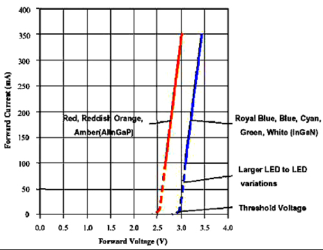
A small voltage change results in a exponentially large change in current.
LEDs require additional regulation of the DC to the diodes because the current drawn by LEDs is an exponential function of voltage. As illustrated above, a small voltage change results in a large change in current. It is therefore critically important that the right DC voltage be provided to the diodes. If the voltage is below the threshold, or on-voltage, no current will flow and the result is an unlit LED. If the voltage is too high, the current will go above the maximum rating, heating and potentially destroying the LED. To make matters worse, as an LED heats up, its voltage drop decreases, further increasing current. For these reasons, High Power AC LEDs require a high degree of power conditioning unlike incandescent light sources.

Left: The Cool Lights LED 600 Fixture. Right: Schematic diagram for an LED string with series resistor and linear voltage regulator.
Existing AC LEDs employ additional power conditioning in the head that is either a DC-to-DC Switch Mode Power Supply type (SMPS) with “constant current regulation”, or a Resistor Type with “linear voltage regulation.” While a resistor wired in series with a string of LEDs permits a linear voltage regulator to stabilize the LED current, this approach (used by Cool Lights and illustrated above) has several drawbacks. First, considerable energy is wasted in the series resistors. Second, the linear voltage regulator that converts the supply voltage to the desired voltage for the LED strings maintains a constant output by wasting excess electrical energy by converting it to heat. As such, this approach is highly inefficient and not ideal for battery operation. The same function is performed more efficiently by using DC-to-DC switched-mode power supply (SMPS) in conjunction with a constant current regulator in the light head.

Left: The Litepanel 1x1 LED Fixtre. Right: Schematic diagram for an LED string with constant current regulator.
The SMPS/constant current regulator approach, in contrast, regulates output voltage by rapidly switching a pass transistor (typically between 50 kHz and 1 MHz). In this approach (used by Lite Panels, Mole,
& Zylites and illustrated above) voltage regulation is provided by varying the ratio of “on” to “off” time of the transistor. Since transistors have no resistance when "closed" and carry no current when
"open" almost all the input power is delivered to the load; no power is wasted as dissipated heat. This higher efficiency is the chief advantage of switch-mode power supply when compared to a linear power
supply that dissipates excess voltage in the form of heat to regulate its’ output. In addition to enabling the total LED string voltage to be a higher percentage of the power supply voltage, resulting in improved efficiency and reduced power use, the highly regulated power provided by SMPS also stabilize the light output of High Power AC LEDs over the wide range of voltages provided by batteries as they discharge.

Figure 1(a): schematic diagram for a SMPS type AC-to-DC Converter that converts sinusoidal AC voltage to DC voltage to drive a LED.
Since, LEDs used in motion picture lighting require direct current (DC) be applied to their diodes, to operate them on AC mains power requires some type of AC-to-DC converter. Again, because of their higher efficiency AC-to-DC switch-mode power supplies are almost universally used for this purpose.

Litepanel 1x1s use the Cincom TR70A24 SMPSs Type AC-to-DC Converter (above right)
which boasts a line regulation of +/- 1%, load regulation of +/- 2%, and an efficiency of 84%..
But, as Figure 2(a) below illustrates, the SMPSs used in AC LED ballasts can draw a very distorted current, and can result in current that is significantly phase-shifted with respect to the sinusoidal voltage waveform.
For instance, the AC power supply that Litepanels uses for their 1x1 panel arrays have a Leading Power Factor of 0.62 and generate high harmonic distortion (THD upwards of 68.1%). As such, the AC power supplies of LEDs can have an
adverse effect on power quality similar to that of CFLs described above.
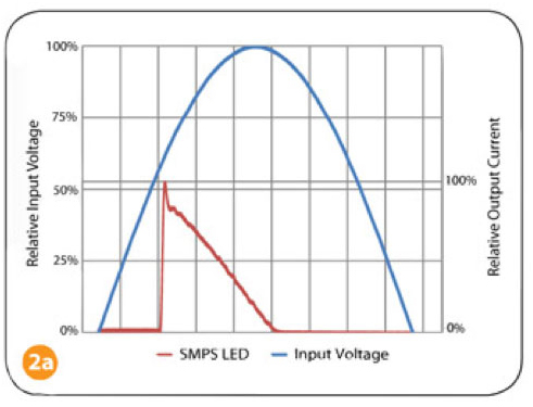
Figure 2(a): Voltage and Current waveforms generated by SMPS type AC-to-DC Converter used to drive AC LEDs.
Like Fluorescent and HMI electronic ballasts, the power quality of SMPS-based AC LED ballast can be improved, but this comes at
the additional cost of adding a power factor correction module to further condition and control the current drawn by the load.
Unfortunately, the manufacturers of High Power AC LED Light fixtures for motion picture lighting applications generally do not
give Power Factor specifications for their products. One would think that the less expensive LED lights would not be pfc, while
the more expensive ones would, but that proved not to be the case in recent testing of fixtures. Over half of the fixtures that
I tested at random (the inventories of Boston area rental and lighting sales companies) were not pfc. With power factors
that range from .45 to .63, these fixtures generated considerable harmonic distortion (THD ranged from 75-85%.)
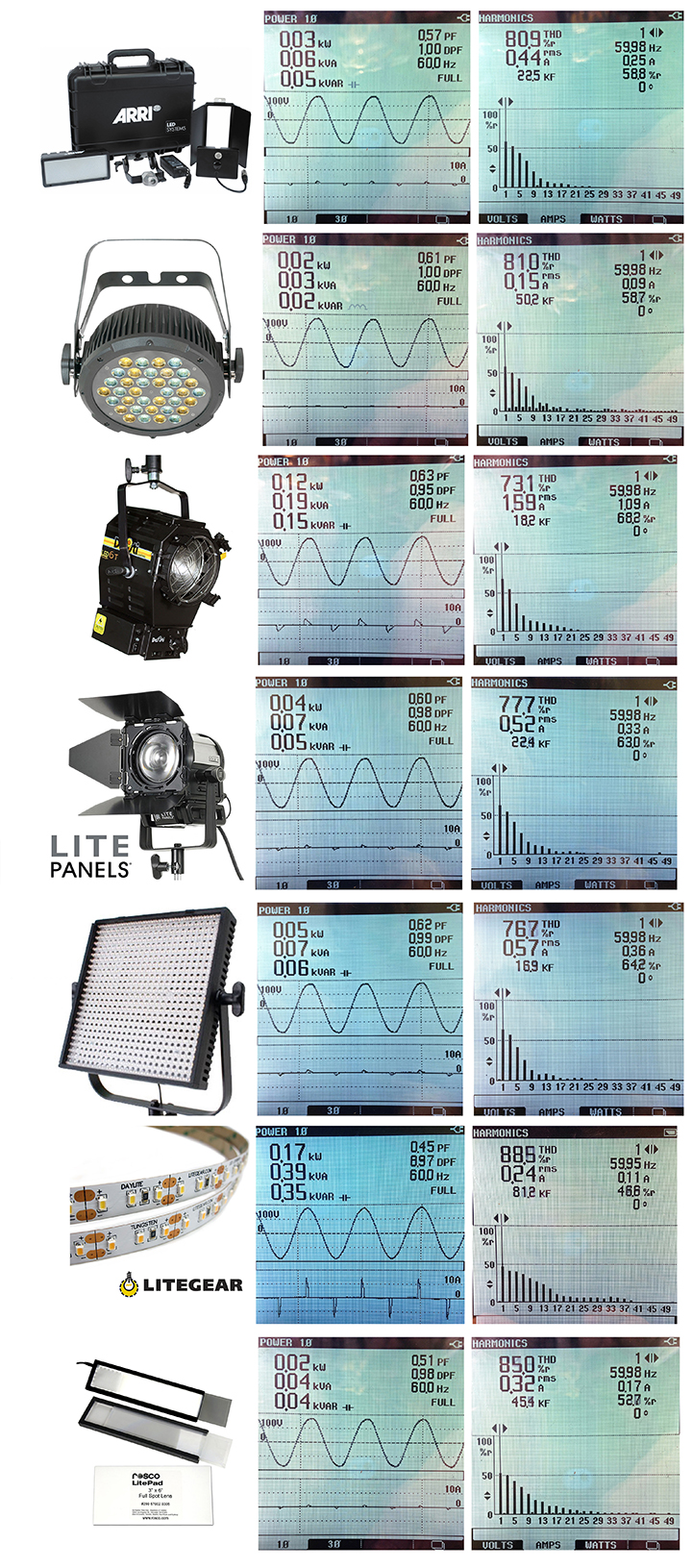
In alphabetical order (top to bottom above) the fixtures were the Arri Locaster, the Chauvet Amber/White Slim Par Pro, the Super
Series of Desisti Studio Fresnels (the F6T & F10T), the Litepanel Sola 4 Fresnel and 1x1 Panel, the LiteGear Lite Ribbons, and
the Rosco LitePad. Even those that were pfc generated harmonic currents when dimmed. For instance, the pfc of the new Litepanel
Astra 1x1 dropped from .99 to .54 when dimmed 50% (THD increased to 83.2%.)

(Bottom left dimmed 50%. Bottom right dimmed to 25%.)
One could argue that the wattage of LED fixtures is so low that the harmonics they draw and kick back into the electrical
distribution system is so low that it does not matter from a practical standpoint. While that is true to a degree, when used as the predominant source of light
in a studio, like the BSkyB studio pictured below, or for a night exterior powered by a portable generator, the harmonics generated by even
small LED fixtures will accumulate and effect their power source adversely.
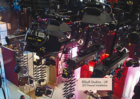
A harbinger of what is to come was the numerous electrical problems encountered at the 2015 exposition of the British Society of
Cinematographers at Pinewood Studios outside London.
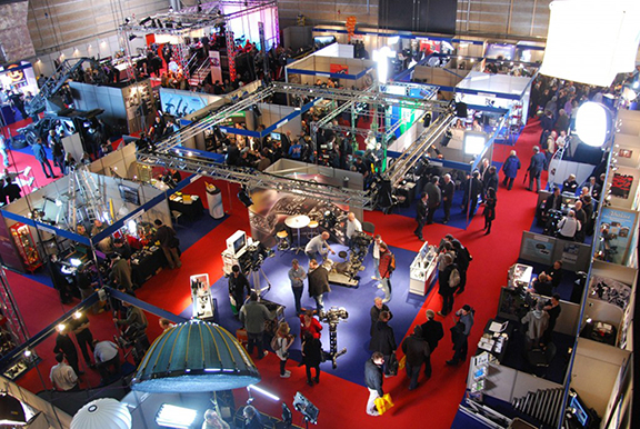
The first show where just about every lighting manufacturer was showcasing a new LED fixture, the show organizers had problems with circuit breakers tripping
unexpectedly. The stage electricians finally isolated the problem to be the higher apparent power and harmonics drawn by the numerous LED fixtures being exhibited.
Versatility and Control
The final issue LED Manufacturers will have to address, before LEDs will be widely accepted in motion picture production, is their lack of versatility and control. The drawback to existing LED light panels is that their light falls off very rapidly and is hard to control. These characteristics make LED light panels only suitable as Key sources in documentary interview set-ups where the Keys are typically positioned close to the interview subject. In that capacity LED light panels (with heavy diffusion) can generate a wonderful soft light that wraps around the interview subject without wilting them. However, in dramatic set lighting, where Key sources must be capable of throwing a distance, LED light panels have only limited applications as fill sources. The broad soft light they put out drops off too rapidly, and is too difficult to control, for them to be effective as a Key or Backlight source in dramatic set lighting. However, progress is being made in the development of a LED light with the versatility and control of a traditional Fresnel instrument. In April 2010, Litepanels introduced a prototype for their Sola-Series LED “Fresnels” at NAB.
While definitely a step in the right direction in developing a production LED Fresnel light, the Litepanel Sola fixtures still don’t quite combine the advantages of LED illumination (cool-burning, energy-efficient) with the characteristics
of a traditional Fresnel fixture.

The 39W Liepanel Sola 4 LED "Fresnel"
With the Sola fixtures, Litepanels has not overcome the basic problems of LEDs discussed above. For instance, Litepanels claims the 39W Sola
4 (pictured above) has the output equivalent to a 125W HMI, but comparing the photometrics published on their website to those of an Arri 125W
Compact Fresnel, the Arri has at full flood nearly nine times the output of the Sola 4 (81 FC at 10’ for the Arri vs. 9.5 FC at 10’ for the
Sola 4). Litepanels doesn’t give CRI ratings for the Sola Fresnels on their website, but when asked they say the CRI is in the 80s – which
is still rather anemic compared to other light sources. And, with a power factor of .6 (see above) the 39W Sola 4 head draws a maximum of 65
Watts and generates a considerable amount of harmonic currents (a Power Factor Corrected HMI has a Power Factor of
.98 and Tungsten lights have unity power factor.) And, while the Sola 4 has an impressive spot to flood range (13 to 72 degrees), spot/flood
capability is not the only characteristic that makes a Fresnel light versatile. Of equal importance is the ability to render clearly defined
shadows and cuts. The ability of Fresnels to render crisp shadows make them ideal for creating gobo effects like window or branch-a-loris
patterns. And, the ability of Fresnels to render clearly defined cuts enables their light to be precisely cut to set pieces and talent.
Finally, Tungsten & HMI Fresnels have sufficient output that the crispness of their shadows or the hardness of their cuts can be varied by
simply adding one of a variety of diffusion material to soften their output if desired. These are the characteristics of traditional Fresnels
that make them extremely versatile, that the Sola "Fresnels" have not been able to emulate. To understand why it is so hard for LED
manufacturers to produce the qualities of a true Fresnel, let's look at those qualities in more detail and how they are achieved in
traditional Fresnel heads.
The Quality of Fresnel Instruments
A Fresnel lens can be regarded as an array of prisms arranged in a circular fashion, with steeper prisms on the edges and a nearly flat convex lens at the center. The prisms near the center of the light source act as "dioptric" lenses that magnify and concentrate
the output of the lamp filament. At the same time, the multiple prisms mounted around the periphery of the lens (above, below, on one side and the other of the filament), act as "catadioptric" lenses that collect and intensify the light and redirect it in the same
plane as the dioptric lenses towards the center. In this fashion, a Fresnel lens bends the light of a source into a column of nearly parallel rays as shown in the illustration below.
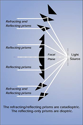
Not only does a Fresnel lens refract the diverging rays of light emitted by a point source (lamp filament) into a highly collimated beam of light, but moving the point source toward the lens floods the beam - increasing its spread and decreasing its intensity.
Moving the point source away from the lens spots the beam, making it narrower and more intense.
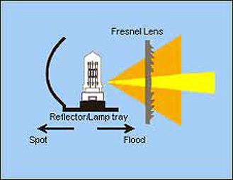
At full flood, the beam is relatively even across a broad sweep (it has no central hot spot), then falls off quickly toward the edges, making for a very even field. As the lamp is spotted in, the rays become less divergent, more nearly parallel. The beam narrows
and gets brighter at the center, falling off rapidly on either side. At full spot, the usable portion of the beam is narrow, about a 10 degree angle.
A common misunderstanding is that the reflector collimates the light of a Fresnel head. In fact, the purpose of the reflector is to double the intensity of its' output. When the light-emitting filament of the bulb is placed near the center of
curvature of a spherical, concave polished mirror reflector, the reflecting surface creates an image of the filament. That image is located in the same plane, but slightly displaced from the filament itself. This has the effect of doubling the amount of light
forward projected from the locale of the lamp filament

In other words, without the reflector, "this reflector light" (the dashed lines in the illustration above) would have been lost in the back of the lamp housing. With a reflector, these rays of light are collected and sent back to their point of origin where they
emanate forward, parallel with the direct rays of light from the filament (the solid line in the illustration above), towards the back of the Fresnel lens where they are together collimated by the lens (for this reason the filaments of the bulbs used in Fresnel
heads are designed with an open geometry to minimize blocking of the retro-reflected light - making them not quite an ideal point source.) Now that all the light that emanated forward and back, emanates forward from a single point within the fixture (the filament
and its mirror image), the light projected forward is doubled. The efficiency of this lamp/reflector design, the collimated quality of it's light output, and the ability of the Fresnel lens to focus the rays of light quickly and easily to obtain a desired intensity or beam width, is what makes the Fresnel
head one of the most versatile fixtures to work with.
For example, a Fresnel head in spot position will "throw" light a great distance, meaning it will illuminate a subject to the same brightness at a much greater distance. This particular characteristic of Fresnel heads is very useful when they have to be used at a
distance. But, Fresnel heads are useful in the making of motion pictures not only because of its ability to focus the beam brighter than a typical lens. What makes them incredibly versatile is that in flood position they also generate light that is crisp and has
a relatively consistent intensity across the entire width of the beam of light.
Fresnels end up used in flood position a lot because that is where it creates its hardest, most delineated shadows (the flood/spot mechanism is often used for little more than to fine-tune intensity.) The more spotted in the fixture, the less sharp the shadow
lines appear. In full spot position, rays from the Fresnel travel more nearly parallel, but some converge slightly and cross one another. This creates fuzziness to shadows cast from an object. If one wants to project a sharp shadow or make a pattern (e.g. the
classic gag below of venetian blinds cast on a wall), one would want to use the light at full flood.

Another common application of a Fresnel in Flood is to create a consistent wash of light over a large area with multiple fixtures. For example, say that, to light a large room, several lights are required because the spread of one is not large enough. Fresnel
instruments spaced evenly apart along one wall of the room can do the job nicely, if the lamps are set at full flood, and the edge of the beam of each light (the 50% drop-off point) is overlapped slightly so that it feathers into that of the next. Overlapping
the beams in this fashion will create an even 100% intensity seamlessly across the whole room.
The highly collimated light of a Fresnel head will enable you to use barn doors to place the edges of the beam of light so that the light does not spill onto adjacent talent or set elements (if they are very reflective.) By closing the two large leaves of a
barn door into a narrow slit you can make a narrow slash of light. The slash can be horizontal - for an eye light for example - or turned diagonally to make a slash across the background. When a very confined, narrow, circular beam is desired, replace the barn
doors with a snoot. Snoots come in different aperture sizes so that you can adjust the beam width. You might use a snoot, for example, to light a set with small pools of light - lighting tables in a cafe for instance.
As an added bonus, it is fairly easy to calculate the intensity and beam diameter of a Fresnel because it has a focused beam (doing so for soft-lights is not so straightforward.) It is for these reasons, that the Fresnel head is still probably the most commonly
used fixture in motion picture production.
LED Fresnels
There are two big hurdles to manufacturing a LED Fresnel head of a practical size - say, the equivalent of a 650W Tungsten Fresnel. First, Fresnel lenses require a point source of light. Second, they are not very efficient and so require a lot of light.
Unfortunately, at this time there is no single-diode LED with sufficient output to serve as a point source for a Fresnel lens, nor will there likely be one in the near future. To understand why that is, let's look at these hurdles in more detail.
At 15 lumens/watt, a 650W tungsten globe will generate 9'750 lumens. But, given the doubling effect of the Fresnel head's highly polished spherical reflector, nearly 19'500 lumens is forward projected onto the back of the Fresnel lens from a relatively
localized source (given the open geometry design of the bulb's tungsten filament it is not quite a point source.) If we take even the brightest LED that exists today, the newest addition (as of 5/11/2011) to the CREE XLamp LED family that in lab tests
generated 231 lumen/watt, it would require an 84.4 Watt LED of this efficiency to match the forward projection of that achieved by a 650W tungsten filament in front of a highly polished spherical reflector. Even if Cree can maintain that efficiency in
what is presently the largest commercially available single-die component LED available, 10Watts, we are still looking at an LED array of at least nine LEDs to equal the forward projection of a 650W tungsten filament in front of a highly polished spherical reflector.
Another reason we are not likely to see a single diode LED with sufficient output is that it is highly unlikely that Cree can maintain that level of efficiency in practical application as the efficiency was optimized at 350mA in the lab test, and had a
correlated color temperature of 4500K. By the time that technology is scaled up to a 10W single-die component LED, and phosphors are added to extend the color temperature to 3200K, you can be sure the end product will generate no where near the same
lumen/watts. Put in perspective, we are still a long way off from having a single-die LED with sufficient output and correlated color temperature to match a 650W tungsten filament in front of a highly polished spherical reflector.
To make matters worse, the inefficiency of Fresnel lenses increase as the source of light diverges from that of an ideal point source. For example, given their open geometry, tungsten lamp filaments don't nearly approximate a true point source. As such
light rays enter the prisms of a Fresnel lens at different angles (angles of incidence), and because some undergo multiple reflections or refractions or are totally internally reflected for this reason, not all of them emerge on the other side of the array.
The width of the vertical step between grooves in a Fresnel lens also block light. This loss does not exist for rays parallel to the optical axis of the grooves. But, for rays making a large angle (20 degree or greater) with the optical axis, the loss can be
significant. The more the source departs from an ideal point source, the greater the angles of incidence, the more light that is blocked by the steps. The more the light source approaches a point source, the more the light output favors the central portion
of the lens, which has greater transmittance. Since there is no single-diode LED with sufficient output to serve as a point source for a Fresnel lens, by default LED "Fresnel" fixtures have to use an array of LEDs. Far removed from an ideal point source,
an LED array not only increases the inefficiency of a Fresnel Lens (requiring a larger array) but also changes the quality of its light output from the collimated source that is desired.


The ARRI L7 LED Fresnels
Regardless of the difficulty, Arri seems to have developed a true LED Fresnel in their new L7 series LED Fresnel heads. At NAB in 2011 Arri introduced the first of their L-Series LED Fresnels: the L7-D, L7-T and L7-C. All three models share the same basic housing and the same 7" Fresnel lens, and all have output comparable in intensity and quality to a conventional 1K Fresnel.
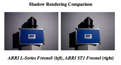
As you can see in the pictures above, that compare the output of the L7 Fresnel to an Arri ST-1 Quartz Fresnel, the L7 Fresnel has clear and defined shadow rendering capability like that of the ST-1 Quartz Fresnel. And, as the pictures below demonstrate, the L7 Fresnel has a spot to flood range similar to that of the ST-1 Quartz Fresnel and excellent field homogeneity in both flood and spot.

And, just like the ST-1 Quartz Fresnel (pictured below), the beam of the L7 Fresnel (pictured above) is easily controlled with barndoors - enabling the light to be precisely cut to set pieces and talent (see far right photos above & below.)

And, given the discernable amount of light the L-Series Fresnel prototypes threw in a show demonstration video from IBEC in the fall of 2010, on what appears to be a 6x6 Ultrabounce rigged 20’ overhead, and under the high ambient light levels of the show hall, it seems the production model L7 Fresnel has more than enough output to waste some to diffusion and color gel if one so desires (a shortcoming to most LED panels is that they have barely enough output – and certainly none to waste.)

Since the L7 fixtures are in the proto-type stage (production models are due soon), Arri is being very reticent about how they are able to accomplish the characteristics of a true Fresnel from a multi-emitter driver. To speculate, I would have to guess they are using
a simple lens system - possibly like the one illustrated below.

By moving a Fresnel lens forward and back in relation to an assembly consisting of an LED Array and a Condenser Lens with an extremely short focal length, the focal point of the Condenser lens moves in relation to the Fresnel lens much like the lamp/reflector
assembly of a traditional Fresnel Head. This would have the effect of spotting and flooding the light output of the LED Array much like a Fresnel spots and floods the output of a point source. Of course this is nothing but speculation, until we are able to get
our hands on an actual production model of the Arri L7 LED Fresnel.
Where the L7 models differ is in terms of color temperature. The D model outputs a daylight-equivalent 5600 K, the T model a tungsten-equivalent 3200 K, and the top-of-the-range C model offers total color control.
With the L7 series, Arri achieves the best color rendition I have seen yet from a multi-emitter fixture. By blending color with a highly sophisticated LED engine, the L7 series is able to overcome the generally poor color rendering
capabilities of other LED fixtures (both remote phosphor and multi-emitter.) Both the 3200 K and 5600 K color temperature models offer a CRI and CQS greater than 90 so skin tones, costumes and scenery appear more life-like.
The L7-C's fully tuneable white light can be adjusted for different skin tones, camera sensors and mixed-light environments, while specific color shades can be matched through full gamut color mixing. Unlike other LED fixtures, this level of color
control does not involve compromising the quality of the light field: the L-Series is unique in combining uniform light and single shadow rendition with absolute control of color attributes.
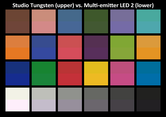
Split Macbeth chart: each color patch shows the visible effects of studio tungsten light in the top half of the patch, and a representative multi-emitter LED lighting instrument
in the bottom half.
Note: this is not the L7 but results typical of the best of the multi-emitter LEDs up to the release of the L7s.
An added benefit to using a color blending multi-emitter LED engine is that the mix of different color emitters can be adjusted to compensate for the
inevitable color shift and diminished output of the LEDs with age. Using an internal optical sensor, the L7's firmware performs this calibration function at switch-on thereby
assuring consistent realistic color rendition throughout the fixture's life and between fixtures - which means there won't be a variance in color between fixtures when talent walks
out of one key and into another, or when using multiple L7s to create a wash up a cyc or backdrop.

There are two alternative cooling systems: one passive and the other active. The passive cooling system was designed for broadcast studios. It incorporates no moving parts or fans and is therefore completely silent. The active cooling system was designed to provide a more compact and lightweight option for location work. It uses an extremely quiet (<20 dB) fan and weighs 10lbs less than the studio version.

The location fixture carries an IP54 rating for weather resistance which means that it is protected from falling rain and splashing water, and that the internal electronics, optics and LEDs are protected from dust, dirt and humidity - making it a very robust fixture that will stand up to the rigors of location production.

All the L7s feature Power Factor Correction with a near unity Power Factor of .91. Which means that the 200W fixtures will draw no more than 1.98A at 120V (220W) and cause virtually no Harmonic Distortion.
Since it creates virtually no line noise, you will be able to power nine 200W L7s on the 20A circuit of a portable generator without a problem.
To assure that they are not quickly rendered obsolete by the rapid advances being made in LED chip efficiency, the Arri L-Series LED Fresels are designed to be an expansible platform, with replaceable parts, that can incorporate
future developments in LED technology. Not only, do the heads allow for the incorporation of more efficient LED chips when they become available (or when the lumnen output of the original ones drop), but the light engine is also
fully upgradeable, ensuring that the fixtures can take advantage of technology advances as they happen. To accommodate future control protocols (such as ANC), their firmware is also upgradeable through the USB port on the rear of
each unit. They will also be compatible with planned future optic accessories that will expand the L-Series versatility. Able to incorporate future developments in LED technology, the expansible platform of the L7s ensures that
they will have a long useable life and so will assure a return on investment in them. Given the rapid pace of LED Chip development, I can't think of another LED fixture that won't be obsolete in a year or two.
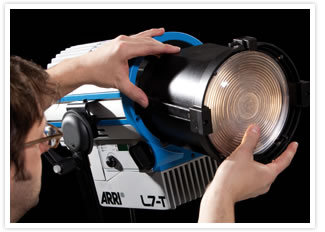
Given the output, the clear and defined shadow rendering, the excellent field homogeneity and the color rendition demonstrated in the show video,
it is evident that Arri has finally engineered the first true production LED Fresnel light (see the 2010 IBEC Show video below or the
NAB 2011 Show Demo for more details (the 2010 IBEC Show video below demonstrates the light quality better, I think.))
Light Emitting Plasma (LEP) Fixtures
Light Emitting Plasma (LEP) is radically new technology that can produce 144 lumens per watt. In contrast, Tungsten Halogen bulbs produce 15 lumens per watt, LED emitters produce between 65 to 85
lumens per watt (in practical applications), and HMI bulbs produce 90 Lumens per watt. In addition to their intense "flicker-free" output, LEP lamps provide a continuous spectrum that is almost identical to Daylight,
long life, and a ruggedness that outperforms other lamps. These characteristics of LEPs make them an ideal source for motion picture lighting applications.

One way to think of a LEP bulb is as a tiny (less than 9 millimeters) discharge lamp. But, unlike an HMI bulb it does not have electrodes. Instead of applying a voltage and drawing a current through the
lamp to create light as does an HMI, the energy that creates light in an LEP comes via a high frequency RF transmitter. The RF waves heat the materials inside the lamp and bring those materials to a
plasma state so that the lamp emits a "flicker-free" light.

The Photon Beard Nova 270 (left), a "Hive" of Hornet 180s (center), and the Helio 270 (right.)
At present there are three motion picture LEP lamp heads on the market: the Photon Beard Nova 270, the Helio 270, and Hive Lighting’s Hornet 180 pictured above. All three lamp heads use the same Luxim
Plasma Emitter behind Fresnel lens. The Photon Beard Nova 270 and Hive Hornet 180 can be operated on batteries at 28 Volts or off a Universal (90-305Vac, 50/60Hz) AC power supply (the power supply is
separate in the case of the Photon Beard Nova 270. The Helio 270, by comparison is a stripped down, more robust location production instrument that offers a built-in 120V/60Hz AC power supply (no DC option)
with near unity (.99) Power Factor. As such, the Helio 270 is nearly half the price of the other two heads.
How LEPs work
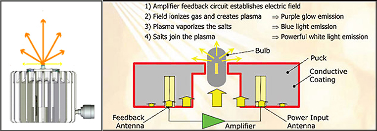
Like an HMI, the LEP bulb is made of quartz and filled with an inert gas, Metal Halide salts, and a very small amount of Mercury. The bulb is partially embedded in a ceramic disc attached to a finned heat sink.
The package consisting of the bulb, ceramic disc (puck), and heat sink is called the “emitter,” and acts as a resonant cavity for the RF energy and the source for the light emitting plasma. A separate “driver”
amplifies high-frequency energy, that a "resonator" focuses on the plasma. The radiated energy ionizes the gas in the quartz envelope and free electrons, accelerated by the electrical field,
collide with the gas and metal atoms, creating a plasma ball. Some electrons circling around the gas and metal atoms are excited by these collisions, bringing them to a higher energy state. When the electron
falls back to its original state, it emits a photon, resulting in visible light. Since the excitation of the plasma is at very high frequency (> MHz), thousands of times faster than film or shutter speeds, the light
output is "flicker-free" at all speeds and shutter angles.

Like an HMI, the stages of excitation are demarcated by changes in the color and intensity of the light put out by the emitter. Upon ignition, as the electric field ionizes the gas molecules, the lamps emits a dim
purplish light which gets gradually brighter of over a period of about 8 seconds as the plasma grows. When the plasma reaches sufficient power to vaporize the Metal Halide salts there is a half second flash of blue
light, that gives way to a bluish white as the salts begin to join the plasma. As more and more of the Metal Halide salts join the plasma the light output grows to an extremely intense full spectrum white light of
about 5300 degrees Kelvin. The whole ignition process takes no more than 20 seconds.
This different method of transforming electricity into light has multiple benefits over the conventional way it’s done in HMI and LED luminaries.
Near perfect CRI (94+): colors are more vibrant and natural looking.
Continuous color spectrum: colors reproduce accurately on screen. Color meters are able to make accurate CT and green/magenta readings
Longer lamp life: an LEP bulb will run 7 times longer than an HMI bulb before exhibiting the same lumen depreciation. Unlike LED fixtures, the color temperature of an LEP bulb
drops just 500 degrees Kelvin in 10’000 hours.
More efficient uniform light output: The pill sized LEP bulb is an almost ideal point source for Fresnel type heads.
Increased energy efficiency: a LEP fixture uses 75% less power than a comparable HMI fixture.
Greater light output: a 273 W LEP fixture has a light output comparable to a 575W HMI.
"Flicker-Free" at all speeds: continuous output that is not dependent on line frequency
Quiet Operation: unlike LED Fresnels there are no cooling fans.
Compact & Robust:
since the plasma light source is very compact, head designs are more compact with greater performance than larger ones.
Let’s look at some of these benefits over HMI & LED luminaries in more detail.
Color Rendering
LEP lamps have very high CRIs (94+.) But, more important than their high CRI ratings, LEP lamps generate light with a continuous color spectrum. If we compare the spectral power distribution graphs of natural
daylight and LEP lamps below, we see that, except for very brief drop outs at approximately 410 nm and again at 451 nm, the light output of LEP lamps is almost identical to natural daylight.

As can also be seen in the spectral distribution graphs above, Plasma lamps have a much more continuous color spectrum than even the best LED luminaries on the market today. For instance, LEP lamps, unlike LED lamps,
generate light at wavelengths shorter than 425nm - which means that violet colors render well. And, unlike LED lamps, LEP lamps also output in the medium blue-cyan-turquoise range from about 465-510nm so aqua-type
colors render well by comparison. Skin tones and warm, amber-yellow colors stand out under LEP lamps because of the strong presence of their complementary colors. And, since the output of LEP lamps extend all the
way out on the long-wavelength end (well beyond the 600 nm cutoff of LEDs), pinks, reds, oranges, and other long wave-length colors look vibrant under LEP light where they tend to look a little dull under LEDs. As a
continuous spectrum source, colors not only appear more natural and vibrant under LEP lamps than under LED lamps, they also reproduce more accurately on the screen since, as is also evident by the spectral distribution
graphs above, the output of LEP lamps matches the spectral sensitivity of film emulsions and digital sensors. Plasma lights deliver the same true-to-life color rendition previously achievable only with full-spectrum
Daylight or HMI sources.
As an added bonus, color meters, like the Minolta III F, that make their calculations of the Color Temperature (CT) based on a light sources continuous spectrum, are able to generate accurate reading of the CT and Green/Magenta of LEP lamps. As we saw above, color meters are completely useless with LEDs.
Lumen Depreciation, Color Shift, & Lamp Life
In contrast to HMI lamps that use electrodes connected through the quartz envelope to transfer the energy necessary to vaporize the metals in the envelope, a LEP lamp radiates the energy through the quartz envelope. Eliminating electrodes in this
fashion offers several real benefits. First, since, electrode deterioration is usually the limiting factor in the lamp life of HMI bulbs (the gap between the electrodes widens to the point that the ballast can not create enough electrical potential
to jump it), LEP bulbs last much longer - between 65,000 and 100,000 hours before ignition failure. Second, with no electrodes to deteriorate and blacken the inside of the quartz envelope, a LEP bulb exhibits very little lumen depreciation over
its long life. Finally, the cooler ignition and operating temperatures at which LEP lamps operate greatly reduces the devitrification of their quartz envelope. The end result is that LEP lamps remain brighter longer and have much better lumen
maintenance than even LED luminaries.

Without electrodes, there is also no arc gap in an LEP lamp, as there is in an HMI globe, that widens over time and results in an increase in arc voltage and on some ballast types an increase in lamp power that results in a drop in color temperature.
Even more significant are the complex chemical reactions between the electrodes (again not present in LEP) and metal halides which also result in color shifts. As a result the color temperature in LEP lamps is much more consistent over longer spans
of time - dropping in 10’000 hrs as much as a HMI bulb does in 500 hrs. Like LEDs, LEPs will keep on producing light at declining levels but at a much more gradual rate and shift in color. For this reason, it is more practical to measure the useable
“lamp life” of an LEP using the same criteria as an LED rather than that used for conventional lamps like HMIs.
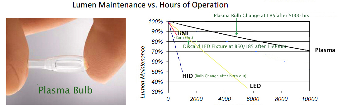
If we apply the same L85 criteria to LEPs that we applied to LED lighting luminaries, their rated lamp life would be an unparalleled 5000 hrs (compared to 750 for HMIs and approximately 1500 for LEDs.) In other words, the interval in which the output of an LEP drops-off of to 85 percent of its’ original value (L85) is 5000 hrs. Unlike an LED, the bulb of an LEP can be replaced after reaching low-light failure, so the fixture does not have to be thrown away.
With such imperceptible drop in color temperature and lumens over their useable life, LEP lamps offer many practical benefits that HMI & LED lights do not. For example, it is possible for head manufacturers to compensate for variances in bulb manufacturing by “tuning” their output to exact specifications so that there is very little deviation between heads. If “tuned”, the lumen maintenance of LEP bulbs is such that, there will be hardly perceptible differences between lamps - even between ones with old and new bulbs. HMI lamps, do not offer the same possibility.
Why would there be a variance between new bulbs in the first place? In the manufacture of both HMI and LEP bulbs, the manufacturer must dose (fill) their bulbs with tiny quantities of numerous chemical elements and metals. Because this is extremely
difficult to do consistently in a manufacturing process, there are inevitably differences in color temperature from bulb to bulb right off the production line. For example, after many years of manufacturing HMI bulbs, Osram is still not able to
dose HMI bulbs so that they match in color temperature or CRI. While the quality control of LEP bulbs is better, there is still some variance in the color temperature from bulb to bulb right off the production line.
What makes it possible to tune LEP bulbs, but not HMI bulbs, is the fact that their color temperature rises very rapidly when they are dimmed even slightly. While this is a disadvantage if one wants to dim the lamps (scriming is recommend instead),
manufacturers like Helio take advantage of this characteristic of Plasma to individually "tune up" their heads to a consistent 5500 degree Kelvin without an appreciable loss in output (HMI lamps, do not offer the same possibility.) Once tuned, the lumen depreciation of LEPs, compared to other light sources, is such that there will be hardly perceptible differences between old and new bulbs.
After tuning the color output of their heads, the almost imperceptible drop in color temperature and lumens over the useable life of LEP bulbs, means that the Helio LEP lights offer many practical benefits that HMI & LED lights do not.
For instance, the consistent color of a tuned LEP lamp assures that the color of wardrobe and skin-tones will not change as talent steps out of one Helio 270 Key and into another. Or, that there will be inconsistencies in color between Helio Space
Lights when multiple fixtures are used to wash a wall or cyc. Finally, LEPs in general do not require the active microprocessor color control that is required to assure consistent color rendition in LEDs. Absent such microprocessor based color
management systems, LEP fixtures like the Helio 270 can be considerably less expensive and more robust than LED luminaries. The biggest cost benefit to LEP lights in general, and the Helio 270 in particular, has got to be the savings in not having
to replace lamps every 750 hrs (HMIs) or the entire fixture when its' emitters reach low light failure (LEDs.) Where a 575w HMI globe typically retails for approximately $150.00, the 5000 hr L85 lamp life of an LEP bulb is equal to seven HMI globes, which amounts to a savings of $1050.00, or nearly half the cost of the Helio 270 Plasma lamp head.
LEPs and Fresnel Lenses
Efficient and very compact, LEP bulbs work extremely well in Fresnel type optical systems. The result is more light output, of a better quality, for less power consumption, when compared to HMI and LED light sources.

The Helio 270 with Luxim LIFI Plasma Emitter
and 175mm Fresnel Lens
When the pill sized LEP bulb in mounted in the puck, the emitting area is no more than 1/4" x 1/4"
and all of its’ output is forward directed within a 60 degree angle. In this configuration, the 273W LEP bulb will deliver 14000 lumens. Such a highly localized forward directed light
is ideal for Fresnel type instruments.

As close an approximation to the ideal point source that exists today, fewer of the light rays emitted by an LEP bulb are lost in or blocked by the facets of a Fresnel lens. The reason for this is that a greater proportion of the light output of an LEP bulb is on the optical axis of the lens, and therefore fewer of the rays will be blocked by the vertical steps between the grooves in the lens. And, since more of its light rays enter the prisms of the lens on axis, fewer undergo multiple reflections or refractions or are totally internally reflected. Finally, where an LEP approaches an ideal point source, its light output favors the central portion of the lens, which has greater transmittance. For these reasons, 90 percent more of the output of an LEP lamp will be transmitted through a Fresnel lens than that of a tungsten filament lamp, making it a more efficient system. For these reasons, LEP emitters (unlike LED arrays) make an almost ideal source for Fresnel instruments.
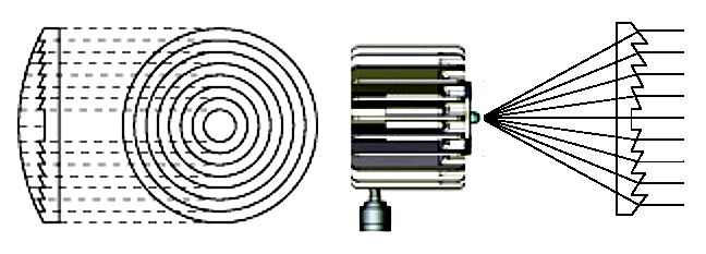
The light output of LEP Fresnels, like the Photon Beard Nova 270 or the Helio 270, is highly collimated, very clean and crisp making it great for cutting shadows or gobo effects. It is easily controlled by barn doors and flags and so can be easily cut off highly reflective set elements.

It’s light field in flood is uniform across a wide angle making it ideal for lighting large areas, and it can be spotted to throw light a great distance. These characteristics of LEP Fresnels, make them extremely versatile and much better than LED panels to serve as a Key or Backlight source in dramatic set lighting.
Power Efficiency
A LEP bulb can produce 144 lumens per watt. In contrast, Tungsten Halogen bulbs produce 15 lumens per watt, LED emitters produce between 65 to 85 lumens per watt (in practical applications), and HMI bulbs produce 90 Lumens per watt. This unparalleled light output, coupled with the greater efficiency it brings to Fresnel lenses as a result of its approximating an ideal point source, make LEP Fresnels the most efficient Fresnel lamp heads available today by far.

For instance, the Helio 270 LEP lamp head draws only 2.27 Amps at 120V, yet has an output comparable to that of a 575W HMI. That works out to be 75% less power than the 9 Amp draw of a 575W HMI with standard
electronic ballast. A number of practical benefits come as result of the efficiency of LEP technology.
In studio applications, the greatly reduced power consumption of LEPs translates into greatly reduced costs in the build out and operation of studios. Not only is the electrical service required greatly reduced, money is also saved on
the power bill. With higher efficiency, the lamp head draws less power, the fixture produces less heat, and so the studio requires less A/C, which means even less power consumption.
On location, you will be able to generate more light on standard wall circuits and generator circuits than has ever been possible before. Able to operate eight 270W LEP instruments on a single 20A circuit, LEP technology
makes it possible to get the output of a 4k HMI from a single wall or generator outlet. When it comes to operating lights on portable gas generators, the greater efficiency of LEP technology is only half the story.
The other half is the fact that LEP lamps, like the Photon Beard Nova 270 and the Helio 270, are Power Factor Corrected (PFC.) The power supply used in the Helio 270, for example, has a Power Factor of .99, making it a near linear load. As a result, the Helio 270 uses power more efficiently, minimizes return current, and generates virtually no line noise.

As the oscilloscope shots above comparing the current and voltage waveforms of the PFC Helio 270 with an equivalent wattage of non-PFC LEDs illustrates (current is represented here as the voltage drop on a 1
Ohm resister), the PFC circuit of the Helio 270 reduces the amount of current drawn, aligns it with the voltage, and induces a smoother power waveform. For these reasons, the PFC power supply of the Helio 270
enables a portable gas generator to operate more heads than it could otherwise. Where, as we shall see below, it is as much the Harmonic Noise that non-PFC HMI, Fluorescent, and LED power supplies (ballasts)
kick back into the power stream, as it is their higher Apparent Power, that limits the total number of them that can be reliably operated on conventional generators; the efficiency and near unity Power Factor
of the Helio 270 means that you can operate more of them on portable gas generators. For instance, you can operate four 575W HMIs on a 6500W portable AVR generator, where you can operate 23 Helio 270s (each
with an output comparable to a 575W HMI). And, if the generator is one of our modified Honda EU6500is Inverter generators, you will be able to operate up to 27 Helio 270s on its enhanced 7500W output. I think
you would have to agree, that is a major increase in production capability (use this link for details.)
A Robust Location Light Source
Plasma emitters use solid state, hardened components that improve their reliability under harsh location production. Plasma bulbs are rugged and vibration resistant, and so will not break or explode inside expensive lighting heads. Since the LEP emitter is extremely compact, in the case of the Helio 270 the emitter, driver, and power supply all fit in the lamp head, eliminating the need for a separate ballast connected by header cables (the acknowledged Achilles heel of HMI systems.) Finally, with much lower UV emissions, LEPs do not require elaborate and ultimately finicky safety switches. In total, LEPs have an order of magnitude better reliability than conventional HMI lamps while offering the intense beam and the colorful spectrum needed for stage, studio and theatrical lights.
Conclusion
Where we are a long way off from having a single-die LED with sufficient output and correlated color temperature to match HMIs, LEP lamps are the most cost effective alternative to expensive HMI Fresnel systems when
it comes to generating daylight balanced light. This feature of LEPs benefits Red users, as well as users of DSLRs, in particular.

The Helio Space Light with three 270 Luxim LIFI Plasma Emitters
has a daylight balanced output equivalent to a 6kw Tungsten Space Light
One downside to lighting for the 5000K native color balance of CMOS sensors in the past has been that it requires an all 5000K balanced lighting package and HMIs are considerably more expensive to buy or rent than
other light sources and not available in popular studio configurations like Space Lights. Kino Flo fixtures, particularly the Parabeams, are a cost effective alternative to HMIs because they can use either 3200K or 5500K tubes. But, the drawback to
fluorescent fixtures (like LED fixtures) is that they generally have a very broad soft light output that drops off rapidly which means the units need to be positioned close to the subject they are lighting. This characteristic has always made them
better suited to lighting documentary interviews than dramatic scenes.
With a 5300K output comparable to that of a 575 HMI Fresnel, the Helio 270 in particular offers the same benefit of being a less expensive alternative to HMIs, but also offers the added benefit of being more versatile than a Kino Flo or LED fixture.
Not only does it offer the capacity of traditional Tungsten/HMI Fresnels to throw and control its light output (making it a more suitable Key and Backlight source for lighting dramatic scenes), but it also has sufficient output to bounce it or waste
some output to diffusion material to make it softer (existing LEDs put out barely enough, with none to waste.) Plasma technology in general is proving to be a better fit with CMOS Sensor based imaging systems, especially for studio lighting applications, than both LED and HMI.
LEPs offer the capacity to provide both hard crisp light that will throw a distance and is easily controlled, as well as offer soft light in Space Light configurations, making it more versatile than Fluorescent, HMI, or LED light for daylight balanced studio production with CMOS sensors.
__________________________________________________________________
Review
To review, the lighting loads placed on generators fall into three basic categories. The tungsten filament of lncandescent lights have no inductive or capacitive properties, but merely create resistance in a circuit.
The voltage and
the current are in-phase, meaning that the peaks and valleys of their sine waves will occur at the same time. A purely resistive load has a power factor of 1.0 (also
called a unity power factor or 100% power factor). When an AC load involves coils, such as those in a magnetic HMI ballast, it creates inductance as well as
resistance. When there is inductive reactance present in a load (an induced current that opposes the flow of the primary current), the phase of the current will be shifted so that its peaks
and valleys do not occur at the same time as those of the voltage.

Voltage/Current phase syncrhonization of lighting loads:
Incandescent Lights (top), Magnetic HMI Ballast (middle), non-PFC HMI Ballast (bottom)
Inductive reactance causes current to lag behind the voltage. The degree to which the two waveforms (current & voltage) are put out of phase depends on the relative amount
of resistance and inductance offered by the transformer and the number of capacitors built into the ballast to counter the inductance. The more they are out of phase, the
lower (poorer) the power factor (with a PF commonly between .7 and .9.) If the load has a large capacitive component (electronic ballasts), capacitive reactance likewise
puts voltage and current out of phase. However, capacitive reactance acts on the waveform in a way opposite to inductive reactance - it causes current to lead voltage. Again, the more the
two wave forms are put out of phase, the lower (poorer) the power factor (with a PF commonly below .6.)
As we have seen, when a sinusoidal voltage is applied to a load through a distribution system, the load, depending on its Power Factor, may or may not affect the quality of the current traveling though the system.
With an incandescent light (a resistive load), the current drawn by the light is proportional to the voltage and impedance and the current waveform follows the envelope of the voltage waveform
having a negligible effect on the quality of power in the distribution system. This type of load is referred to as a linear load (loads where the voltage and current follow one another without
any distortion to their pure sine waves).
ILLUSTRATION COURTESY OF ELECTRICAL CONSTRUCTION & MAINTENANCE (ECM) MAGAZINE

Shown are plots of different linear load currents,
Ip is a pure resistive circuit current.
IL is a partially inductive (lagging) circuit current.
IC is a partially capacitive (leading) circuit current.
In contrast, loads like magnetic and electronic HMI and fluorescent ballasts, put the primary current out of phase with the voltage and generate secondary harmonic currents that are dumped back into the distribution system and adversely affect the quality of power. These loads are classified as
nonlinear loads. Where it is these harmonics that affect the quality of power in the distribution system and hence the operation of our production equipment, a basic understanding of harmonics is essential to providing safe and reliable power on set.
__________________________________________________________________
Harmonics
Harmonic Basics
When dumped back into the electrical distribution system of a generator, harmonic currents can combine with the fundamental (60 Hz) current to create distortion of the voltage waveform similar to what can be seen below.
When looked at on an oscilloscope, the current waveforms of nonlinear loads appear like the non-sinusoidal waveform above because they contain additional waveforms of the secondary currents superimposed upon the primary sinusoidal current waveform, creating multiple frequencies within the normal 60-Hz sine wave. The multiple frequencies are harmonics of the fundamental frequency.
Undistorted Fundamental Pure Sine Wave
The current sine wave above represents what is called the fundamental wavelength. This is how the power waveform should look on an oscillosocpe in an ideal
situation. However, in practicality nothing is ever ideal. For example, as we saw above, solid state electronic components found in electronic HMI and Kino
Flo ballasts use only portions of the sine wave. These devices then return the unused portions as harmonic currents.
Isolated Fundamental and its' Third Harmonic
Since, most portable generators use two pole Rotors and so have an even number of north and south poles, all even number harmonic currents cancel out - leaving only odd number harmonics. In a 60 Hz
set, the 3rd harmonic occurs at 180 Hz, the 5th at 300 Hz, 7th at 420 Hz, and so on. While modern test equipment is able to detect up to 63 orders of harmonics, there is no doubt among electrical
engineers that there are higher frequencies present that are undetectable. The diagram above shows the fundamental sine wave (in blue) and the third order harmonic (in green) together for comparison.

Third Harmonic superimposed on Fundamental as it would appear on oscilloscope.
When the wave is measured on an oscilloscope, it will not appear as two waves but one (depicted above in blue.) The harmonics are super-imposed onto the
fundamental wave creating a ripple effect. These ripples are known as harmonic distortion. Below is a diagram showing the fundamental and 3rd order harmonic
waves super-imposed for the two predominant types of non-linear lighting loads - inductive and capacitive.
ILLUSTRATION COURTESY OF ELECTRICAL CONSTRUCTION & MAINTENANCE (ECM) MAGAZINE

The waveforms on the left illustrate the effect of the 3rd harmonics of capacitive loads (where current leads voltage) like the SMPS-based ballasts used for
HMI, fluorescent, and High Output AC LED lights. The waveforms on the right illustrate the effect of the 3rd harmonics of an inductive load (where current lags voltage) like
the magnetic ballasts of older HMIs and fluorescent practicals.
If we were to add the effect that the 5th, 7th, 9th, etc. harmonic currents would have on the waveform, we would see a further distortion of the waveform
from its' ideal sinusoidal shape. In the case of highly capacitive non-linear loads like electronic HMI ballasts, we would see a further squaring off of the power waveform like that in the animated illustration below.

The Adverse Effects of Harmonics
The waveform distortion discussed above can cause problems in generators ranging from errors in voltage regulation, generator and load overheating, and inaccurate instrument readings.
Both voltage and current may have harmonic components.
The more harmonic content in a generated wave, the more distortion from a pure sine wave occurs. If the voltage waveform distortion is severe, it can cause voltage regulator
sensing problems and inaccurate instrument readings. The major difficulty caused by current components is heat generated in the generator’s winding, core, and rotor. Since
generator ratings are limited by allowable temperature rise, harmonics act as de-rating factors. Since our objective is to operate as many lights as possible on small portable
generators, let’s look at the adverse effects of harmonics on generators that cause their load limit to be de-rated.
Voltage Waveform Distortion
In theory, each harmonic current in an electrical distribution system will cause a voltage at the same harmonic to exist when the harmonic current flows into an
impedance. For example, a 5th harmonic current will produce a 5th harmonic voltage, a 7th harmonic current will produce a 7th harmonic voltage, etc.
Because a distorted current waveform is made up of the fundamental plus one or more harmonic currents, each of these currents flowing into an
impedance will, in theory, result in voltage harmonics appearing at the load bus, a voltage drop, and distortion of the voltage waveform.
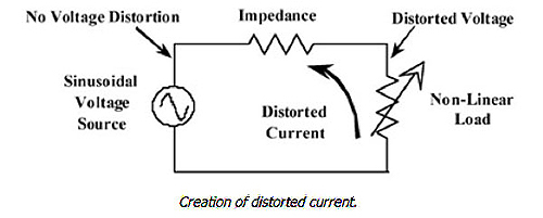
Each harmonic current in the electrical distribution system will cause
a voltage at the same harmonic to exist when
the harmonic current flows into an impedance.
As can be seen in the illustration above, voltage distortion will be greatest at the loads themselves, since the harmonic currents are subjected to the full system
impedance (generator, cables, etc.) at that point. In other words, the voltage will be the least distorted nearest to its source and will become more distorted
nearer to the load, where the harmonic current encounters the greatest impedance. This is a characteristic most often misunderstood about distribution systems
with a high THD. It means that even if voltage distortion levels are low at the power source, they can be unacceptably high at the loads themselves.
In practice, when you plug a HMI light into a wall outlet you need not be concerned about current harmonic distortion producing voltage distortion. However, it is an all together different situation when plugging a HMI into a small portable generator. That is because the magnitude of voltage waveform distortion in a distribution system depends upon three factors: the impedance of the power system, the quality of the original applied power waveform, and the relative size of the nonlinear loads with respect to capacity of the power generating system. Let’s look at each one of these factors in more detail.
Inherent Applied Voltage Waveform
A pure sinusoidal voltage, like the one represented below, is a conceptual quantity produced by an ideal AC generator built with finely distributed stator
and field windings that operate in a uniform magnetic field.
Since in reality neither the winding distribution nor the magnetic field can be uniform in a working AC generator (not even power plant generators), voltage waveform distortions exist, and the voltage-time relationship deviates from our conceptual pure sine function. Typically, the distortion of grid power is very small (less than 3%), but nonetheless it exists.
As we saw at the outset, it is an all together different situation when it comes to generators. Since, there is a direct trade off between generator cost and quality of the power waveform,
voltage distortion in the original power waveform varies greatly between the types of generators (see representative waveforms and chart below.)
WAVEFORM ILLUSTRATIONS COURTESY OF HONDA POWER PRODUCTS

Waveforms Left to Right: Grid Power, Brushless Generator, AVR Generator, MSW Inverter Generator, PWM Inverter Generator
In conventional AVR generators the shape of the voltage waveform is directly correlated to the physical shape of the Rotor pole heads. For instance, a square pole head will generate a square
flux wave. Since a square flux wave will generate many odd harmonics in the Stator windings, generator manufacturers shape their pole heads to generate as sinusoidal a voltage waveform as
possible in order to reduce the generation of voltage waveform distortion. To make the flux wave more sinusoidal, the pole tips can be beveled. This increases the air-gap length at the pole tips,
increasing the reluctance, or resistance, of the flux path. To achieve the best flux waveform possible, the pole face is rounded at a radius with a different center than the Stator core.
How carefully a manufacturer physically shapes the pole heads of an AVR generator determines its’ “Waveform Deviation Factor.”

The slightly beveled pole tips of a Honda EX5500 Rotor
Waveform deviation factor, or wave-shape deviation factor, is an indication of the degree that a generated voltage differs from a perfect sine wave. In large gen-sets these factors do not generally exceed 10% of the line-to-line generated voltage at no load. In small AVR generators it can approach 23% in the case of brushless generators.
In the case of inverter generators, how closely their output voltage waveform approximates a pure sine wave is directly correlated to the number of steps that make up the switched waveform.
ILLUSTRATION COURTESY OF JOHN DE ARMOND
Ideal Sine Wave (black), Single Step Square Wave Inverter (blue),
Three Step Square Wave Inverter (red)
The more steps, the more like a sine wave the output can be. However, since each of the voltage steps requires its own voltage supply, its own transistor switch, plus the necessary control circuitry, the voltage waveforms generated by inverter generators vary widely depending on their cost.
The bottom line is that the output of all generators has some degree of waveform distortion. To reduce the generation of voltage waveform distortion, it is important to start with as nearly a pure sinusoidal voltage waveform as possible.

ILLUSTRATION COURTESY OF HONDA POWER PRODUCTS
Total Harmonic Distortion Values for original waveforms of
Brushless (blue), Conventional AVR (green), Inverter (red) generators.
System Impedance
Since harmonic currents react with impedance to cause voltage drop, the magnitude of a voltage waveform distortion caused by a non-linear current demand is a function of the source impedance. In the case of generators, source impedance is not an easily defined value as generator reactance varies with time following a load change.
However, what is certain is that the generator with the lowest internal reactance to an instantaneous current change at a given load will typically have the lowest value of total harmonic distortion under nonlinear load conditions.

To visualize why this is the case, imagine a birds eye view of a 1400 Amp Crawford Studio Unit parked on top of the Hoover Dam next to a Honda EX5500 portable gas generator with Barber Coleman
frequency governor. If you had 2ks plugged into each power source and switched them on at once. Which generating source would be affected the most? The change in load would have no effect on the
turbines of the hydroelectric generating plant. Given the force exerted by millions of gallons of water driving the turbines and the inertia of their mass, they would not be disturbed at all by a small load change.

In the case of the Crawford 1400A Studio Unit, switching on a 2k might create a very slight momentary fluctuation in the engine speed of the 1400A Crawford. But given the mechanical inertia of its large diesel engine and the sophistication of it governing systems, the effect will be negligible. However, given the small mass of the Honda EX5500’s engine and the relative simplicity of its’ governing systems, switching on a 2k load will cause the Honda EX5500 engine to fluctuate for several seconds as the voltage and frequency governors adjust for the change in load.

While exaggerated, this example demonstrates why, depending on the size and design of the generator, it may have 5 to 100 times greater internal reactance to an instantaneous change in load than a power grid transformer. Consequently, non-linear loads which work fine on utility power, will react entirely different when powered by a generator set. And, the generator with the lowest internal reactance at a given load will typically have the lowest value of total harmonic distortion under nonlinear load conditions.
For this reason, voltage waveform distortion as a result of harmonic currents is not a problem on grid power and is for the most part not a practical problem on large film sets. In practice, when you plug a HMI light into a wall outlet you need not be concerned about current harmonic distortion producing voltage distortion. The impedance of the power source is so low, the distortion of the original applied power waveform so small (less than 3%), and the power plant generating capacity so large by comparison to the load, that harmonic currents fed back to it will not effect the voltage at the load bus.
To say that harmonic currents are not a practical problem on large film sets is more of a testament to the industry and the means it has developed to remediate the problem than to say that
harmonics do not exist. Voltage waveform distortion is for the most part not a problem on large film sets because of remedial steps taken in the design of form specific generating and power distribution systems engineered to remediate the adverse effects of harmonic currents. With 2/3 pitch windings, MQ Power studio (Crawford) generators are specifically designed to remediate the most troublesome of the harmonics generated by non-linear loads and as such have specifications for total harmonic distortion (THD) values of less than 7% under full linear load, and of not more than 3% of any given harmonic current. For this reason, and the fact that they offer a comparatively low sub-transient impedance value and are typically oversized for the load, harmonic currents do not cause substantial voltage waveform distortion.
Percentage of Load
However, it is an all together different situation when plugging a couple of 1200W HMIs into a small portable generator that is not specifically designed to remediate the effects of harmonics. Given the comparatively large sub-transient impedance of conventional AVR portable gas generators, and the high THD value of their inherent power waveform (see no load waveforms below), you have a situation where even a small amount of harmonics being fed back into the power stream will result in a large amount of harmonic distortion in its’ voltage. Making the matter worse is that, given the increasing prevalence of non-linear light sources in production, it is likely that the percentage of the generator’s capacity taken up by non-linear loads will be very high given its small size relative to the size of HMIs typically used on these generators (575-2500 Watts.) Small portable conventional AVR generators present a perfect (electrical) storm
where the return of any harmonic currents results in a very high degree of voltage distortion.

Left: Original Grid Waveform w/no load & low THD (>3%)
Right: Original conventional AVR Generator (Honda EX5500) waveform w/ no-load & high THD (@17%)
The means by which the industry has more or less successfully dealt with harmonics - namely the over-sizing of generators, the over-sizing of neutrals, the incorporation of power factor
correction circuitry in large HMI ballasts, and finally the use of generators with 2/3 pitch windings – are generally not available to users of small portable generators as their primary
source of power. It is generally not an option for small independent productions using portable gas generators by necessity to upscale to larger generators; and, given that there is not much that the end user can do to alter the power output panel of a portable gas generator, it is not an option to customize their distribution package for the requirements of higher neutral currents resulting from non-linear loads. All that users of small portable generators can do to remediate the adverse effects of harmonic currents is downsize their lighting package when it consists predominantly of non-linear light sources.

Left: Pkg. of 2-1200 HMI Par w/ non-pfc ballasts & Kino Wall-o-Lite powered by grid power.
Right: Same Lighting Pkg. powered by conventional AVR Generator (Honda EX5500)
Note different effect that the same non-linear load harmonics have on grid power and power from conventional AVR generator.
What we see above is the voltage distortion at the power bus of our distribution system created by the harmonic currents, or "noise", being thrown back into the system by a typical non-linear lighting package. An artifact of this noise, that is evident here and worth noting, is the zigzag saw tooth pattern as voltage ascends from zero potential and descends to zero potential. This zigzag saw tooth pattern is an indication of the existence of high frequency “wavelettes” within the primary sine wave. When interpreting the highly distorted voltage waveform above, it is worth remembering that the square wave depicted on our scope is in fact comprised of many, many voltage spikes, at extremely high frequencies, stacking one on top of the other.

Harmonics making up a Square Wave.
That is, if we were to break out the components contributing to the generation of the square-wave we see on our scope it would be comprised of more than just the three orders of current harmonics depicted in the example above. We would find that it is generated by many many high frequency harmonic currents, each inducing a voltage spike of its' own. Each of these voltage spikes is induced by high frequency harmonic currents being thrown back into the power stream by the electronic ballasts of our non-linear lighting package. The accumulative effect of all these induced spikes in voltage stacking one on top of the other is the square wave with zigzag pattern as voltage ascends and descends from the zero crossover point that we see in the oscilloscope shot above.

Sprectrum analysis of the high frequency Harmonic Currents that create a Square Wave
It is important to realize that the oscilloscope shot above is of the voltage waveform at the distribution bus of the generator "upstream" of the load (a 1200W non-PFC Electronic HMI ballast in this case) and that the oscilloscope probe is reading between hot and ground. While, as we will see below, harmonic currents stack on the neutral return of a distribution system, what we are looking at here is the effect of harmonics currents that are also feeding back up through the distribution system all the way to the generator's Stator and Rotor windings. What this means is that any piece of equipment plugged into this distribution system sees only this distorted waveform as its' power supply.
This harmonic distortion of the voltage waveform exists only in the case of the portable generator power, where it would not in the case of grid power, because of the inherent distortion in the applied voltage and the
relatively high impedance of the generator and distribution system compared to power from the utility grid. To put it in the most simplistic terms, if I had to explain this electrical phenomenon to my 5 year old,
I would say that Ms. Sinusoidal Voltage met Mr. Harmonic Current over Impedance, and had a baby they named Pseudo Sine Wave. While this description is overly simplistic, it drives home the point that this Pseudo Sine Wave is a completely new entity
created from the other two, and is all that equipment on the distribution system will see.
Other Adverse Effects of Harmonics
Without a doubt, as the trend toward HD production continues, the increasing use of personal computers and microprocessor-controlled recording has created an
unprecedented demand for clean, reliable power on set. At the same time a parallel move toward HMI and Florescent lighting instruments is dumping more and
more harmonics back into the power stream. Where, as we have seen, these loads can have undesirable effects on the current wave form of generated power,
an awareness of these effects will help us to build production systems that avoid or mitigate problems, as well as show us how to solve problems should they arise.
Here is a quick summary of other adverse effects that can result from excessive harmonic distortion.
Adverse Effects to the Generator & Distro
Erractic Voltage Fluctuation
As discussed previously, the Automatic Voltage Regulator (AVR) of conventional portable generators maintain the terminal voltage of the generator at a constant value by sensing the output voltage, comparing it with a set value, and correcting any error by suitably changing the field excitation current. Given how it works, the sensing part of an AVR system is the most important part from an operational standpoint.
How the AVR system senses the generated voltage varies from one generator design to another. Regardless of how the voltage is sensed, a considerable amount of harmonic distortion in the terminal voltage will result in the voltage
getting regulated at a wrong level unless the AVR system is specifically designed for non-linear loads. Modern designs on large gen sets that are specifically engineered for non-linear loads use filtering in the voltage sensors,
sense on all the power phases, and use true rms calculation (either using analog electronics or by using digital techniques in micro processors) to avoid voltage regulation problems when serving non-linear loads. Needless to say,
conventional portable gas generators do not use AVR systems of this level of sophistication, and so distortion of the terminal voltage as a result of harmonic distortion results in the voltage getting regulated at a wrong level
(the one exception being the Digital AVR of the new Honda EB10000 - see above for
details.)
Because an AVR system is a closed-loop control system, as the voltage is incorrectly changed, based on the distorted information, it is then even more incorrect and the output voltage finally gets so far off that the generator
ceases to produce an output that is usable.
For example, the rudimentary AVR systems used in portable generators are especially ill equipped to deal with leading power factor loads like electronic ballasts because the harmonic currents they generate create flux in the
armature coils of the Stator that reacts additively with the Exciter flux in the field poles of the Rotor to increase saturation and produce a higher terminal voltage than called for a given load. Consequently, the AVR system
responds erroneously to control voltage by reducing excitation. The end result is that the regulator goes to its minimum excitation capability while the additive excitation of the armature flux from the leading power
factor causes the terminal voltage to continue to rise. No longer controlled by the voltage regulator, the terminal voltage becomes unstable.
Erractic Speed Fluctuation
Another problem that can result from high THD values is the malfunctioning of the generator’s AC frequency governor. As discussed previously, the engine governor system needs a speed feedback signal. In the case of after market engine governors designed for portable gas generators, this signal is generated by measuring the frequency of the sensed output voltage inside the AVR unit.

Voltage notching can create multiple zero crossings
Where this frequency calculation involves zero-crossing information from the waveform, high THD values can cause problems. For example, voltage notching and heavy ringing transients like the ones present in our
distorted waveform (above) create multiple zero-crossings within one cycle of AC waveform. This leads to large magnitude random errors in the frequency signal prepared by the AVR unit for use by the governor unit.
The governor unit gets confused and there results instability of the speed governing system.
In our discussion above, we covered a number of the adverse effects that harmonic noise can have on the generator itself. To review they include over heating, voltage regulation and speed regulation problems. Kevan Shaw’s
You-Tube video “Compact Fluorescent verses The Generator" (discussed previously) clearly demonstrates these effects. It is informative not only for the
point he sets out to make, but also for the point he makes unintentionally. If you will recall, in his video (below), lighting designer Kevan Shaw set out to demonstrate that CFL bulbs have a poor power factor (.5) and
consume double the energy (Apparent Power) for the 18 Watts of light (True Power) they generate. However, his video also clearly demonstrates the severe effect that leading power factor loads can have on the governing
systems of conventional AVR generators.
When Kevan turns off the 18W CFL bulbs one at a time until the generator stabilizes, he is not only demonstrating that 15 – 18W CFL bulbs has roughly the same Apparent Power
(535W), according to the generator’s Watt meter, as a 575W incandescent light; but, also that the maximum Leading Power Factor load a 850W conventional generator can operate
satisfactorily is 270 Watts (15 – 18WCFL bulbs). Looked at another way, 576 Watts of Apparent Power with a Leading Power Factor (16 - 18W CFL bulbs) overloaded the generator,
while 575 Watts of Apparent Power with a Unity Power Factor (the 575W Quartz Leko) did not. What accounts for this difference? Since the load is almost the same (576 & 575
Watts of Apparent Power respectively), the only factor that can account for the generator going berserk with the equivalent load of CFL lights is the harmonic currents that
they generate that the Quartz Leko does not. Without a doubt, Kevan Shaw’s video is a clear demonstration of the adverse effect that harmonic currents have on the
governing systems of conventional AVR generators.
For the same reason that Kevan Shaw was not able to operate more than 270 Watts of CFL bulbs (15 – 18W bulbs), it has never been possible to reliably operate more
than a couple of 1200W HMIs with non-PFC electronic ballasts on 6500W conventional AVR generators. The adverse effects of the harmonic currents they generate, so
graphically demonstrated in Kevan’s video, limits the total amount of Leading Power Factor loads, as compared to Unity Power Factor loads, that can be reliably operated
on conventional AVR generators. So much so that, manufacturers take the type of load that a generator will likely operate into account in determining the continuous
load rating of a generator for a specific market (more on this subject latter.)
Erroneous Readings from Measurement Equipment
The most important factor to consider when using a multi-meter is the method of calculation used in the meter. All of the commonly used types of multi-meters are calibrated to give an “RMS” indication for the measured signal, but arrive at that value using a number of different methods. Unfortunately, most of these methods assume the waveform to be sinusoidal and so when used to measure nonlinear voltages and currents errors occur that result in false readings. Since the consequences of under measurement can be significant - overloaded cables may go undetected, bus-bars and cables may overheat, fuses and circuit breakers will trip unexpectedly - it is important to understand how meters work and why only meters based on "true RMS " techniques should be used on power distribution systems supplying nonlinear loads.
The display of a multi-meter does not indicate the peak of the AC voltage generated, or the AC current drawn by a load, as one
might think. Rather, they
are designed to calculate the root mean square (RMS) of an alternating waveform. Why is the RMS value of voltage or current more important than the
peak value? In order to answer that question, consider what RMS means in practical terms. While it is mathematically the root mean square of an AC
waveform, it is also the effective DC value of an AC signal. Since a DC voltage is essentially constant over time, the work performed at the load
for a DC voltage is also constant – a very effective power source. However, an AC signal is constantly changing in amplitude over time. Therefore
the work done at the load is also constantly changing – a less effective power source. So a good benchmark by which to gauge the effectiveness of
a power source and/or load is the measure of the amount of AC voltage needed to perform the same amount of work at the load as a DC voltage, i.e.
the RMS value of the AC voltage. For this reason, this is how voltage and current is measured.
To understand the logic, think about this in terms of the heating, or over-heating, of a wire. Wire insulation is rated for specific maximum voltage
and current, therefore the heating effect of both is of critical importance to safety. Say in testing the insulation of a wire, it is
connected to a DC source and heated until the insulation starts to break down. It took a specific DC voltage in order to heat the wire to this temperature. Now
the DC source is removed and an AC source is connected instead. The AC voltage that is required to heat the wire to the same temperature, as
the DC voltage, is critical for its' safe usage. Therefore, the RMS value of the AC voltage, or the “effective” amount of voltage needed
to perform the same amount of work (i.e. the generation of heat) as the DC voltage is a valuable benchmark. In a perfect sinusoid there is a specific
relationship between the AC peak, AC RMS and equivalent DC value (shown below.)

If an electrical signal is a pure sinusoidal wave, the peak value for voltage or current is 1.414 times the RMS value. Expressed another way, the RMS
value is 0.707 of the peak value. If the magnitude of a fully rectified sine wave is “averaged” (i.e., the negative half cycle is inverted and the result averaged) the mean value will be
0.636 times the peak value or 0.9 times the RMS value. For a sine wave, these two important ratios relevant to current and voltage measurement can be
derived as follows:

Two out of the three methods used in multi-meters to calculate RMS are based upon these specific relationships of a sinusoidal waveform. They are as follows:
1) Peak Method: The meter reads the peak of the signal and divides the result by 1.414 (square root of 2) to obtain the RMS.
2) Averaging Method: The meter determines the average value of a rectified signal. For a clean sinusoidal signal, this average
value is related to the RMS value by the constant, k = 1.1. This value of k is used to scale all waveforms measured.
3) True RMS: The RMS value of a signal is a measure of the heating which will result if the voltage is impressed across a resistive
load. Modern digital meters use a digital calculation of the RMS value by squaring the signal on a sample by sample basis, averaging
over a period, and then taking the square root of the result.
Each of these different methods will give accurate results for a clean, sinusoidal signal. However, as we have seen, power is not always a perfect sinusoid. Interactions between the supply and load (with all components in between) will cause distortions to power waveforms and thus affect the relationship between the peak of the waveform and its’ RMS value, leading to erroneous measurement by all but True RMS meters.

Let’s take for example, how a meter that uses the averaging method will calculate the RMS value of the current drawn by a 2.5kw HMI with a non-power
factor corrected electronic ballast. So that we start with accurate measurements, let’s first look at the readings above taken by a very high end
true RMS power quality meter, the $3500.00 Fluke 43B. One feature that the 43B offers, that the less expensive averaging mulitmeters do not, is that
it calculates the Peak Factor of a waveform and displays it as Crest Factor. Crest Factor, which is simply Peak Factor by another name is, like
Power Factor, a ratio (the ratio of Peak Value to RMS value.) But rather than relate the effectiveness of a load as Power Factor does, it is used to
relate the quality of a power source. The higher the Crest Factor the more distorted is the waveform of the power source. The closer the Crest Factor is to 1.414
(the Peak Factor of a pure sinusoid) the less distorted is the power. According to the display of the 43B above, the current drawn by a 2.5kw
HMI with a non-power factor corrected electronic ballast operating on grid power is quite distorted with a Crest Factor of 2.6.
Now that we know the Crest Factor we can calculate the Peak Current drawn by the 2.5kw HMI by multiplying the RMS value (35.5A) by the Crest Factor
(2.6). The result comes to 92.3A (35.5Ax2.6=92.3A), which corresponds to the graphic representation of the current on the 43B’s display (the lower
spiked waveform) which appears to barely reach the 100A benchmark of the display. With this level of waveform distortion it is not surprising that
erroneous measurements occur. A meter that uses the Peak Method to calculate RMS (Peak Value/1.414) would display an RMS value of 65.27A
(92.3A /1.414 = 65.27A) in this instance, which is nearly double (184%) the actual RMS value of 35.5A.
What accounts for such a high Peak Current? As discussed previously, the smoothing capacitors in the first stage of the ballast have to charge
in a very brief period of time compared to the overall cycle while voltage ascends to its peak. And since, during this very brief charging period, the
capacitors must charge fully, large amounts of current are drawn in short durations. The end result is that the current drawn from the mains is a
series of narrow pulses that peak before the voltage peaks and whose peak current is typically 5-10 times higher than the resulting DC value.

Top: AC Voltage Waveform, Middle: Rectified AC (dashed line) and Capacitor Charge (solid line.) Bottom: Current waveform drawn by linear loads (dashed line) and current waveform drawn by the smoothing capacitors of non-pfc HMI ballasts (solid line.) Note high peak of current drawn.)
By drawing current in this fashion, the smoothing capacitors of non-PFC electronic HMI ballasts alter the ratio between peak and RMS current that
is the basis by which the first two methods above calculate RMS values, that leads to erroneous reading of distorted waveforms by all meters except “true RMS” meters. To see why this would be the case with multi-meters using the Averaging Method let’s go back to our example of a 2.5kW HMI.
As discussed previously, the Averaging Method entails taking a measurement of the average (or mean) value (0.636 × peak) and multiplying the result by
the form factor k of a sinusoid (1.11). The result is 0.7071 times the peak value, which is displayed as “RMS.” This technique will arrive at an
accurate RMS value when measuring a sinusoid, but will generate erroneous readings of distorted waveforms because the assumptions under which it
operates are valid only for sinusoidal waveforms.

For example, if we were to apply the Averaging Method to what we know about the 2.5kW HMI with non-PFC electronic ballast we find that it
under-calculates the RMS value of the current by nearly 40%. How do we determine this? Let’s stick with ratios for now: if the true RMS
value is 1 and the Crest Factor, according to the 43B, is 2.6 than the peak value is also 2.6. If we were to do the math, the mean value
would be 0.55. A meter using the Averaging Method multiplies the mean by the form factor k of a sinusoid (1.11), which results in an “average
reading, calibrated RMS” of 0.61 (.55 x 1.11 = 0.61) for every unit of true RMS. The true RMS of the 2.5kW HMI in our example is 35.5A, which
makes the “average reading, calibrated RMS” 21.67A (35.5A x 0.61 = 21.67A.) This erroneous RMS value arrived at by the Averaging Method
(21.67A) is 39% less than the measured true RMS (35.5A.) Without a doubt, an error in measurement of this magnitude can have serious
consequences since it may lead to overloaded cables going undetected, bus-bars and cables overheating, fuses and circuit breakers tripping
unexpectedly.
The higher peak current drawn by a non-PFC electronic HMI ballast is just one form of waveform distortion. Another is the square wave caused by flat topping of the voltage waveform as a consequence of the harmonic currents generated by the ballast encountering the high impedance of a generator.

Left: generated waveform without load. Right: generated waveform "flat topped" by 2.5kW HMI with non-power factor corrected ballast.
Consider the square wave of voltage distortion generated by our 2.5kW HMI with non-power factor corrected HMI shown above. Average and peak reading meters would
indicate erroneous values of 129.47V and 96.52 RMS, respectively, compared to the true RMS value of 117.7V. Why is this the case? The voltage drop that
occurs when the harmonic currents generated by the ballast encounter the high impedance of the generator causes the voltage waveform to plateau well
below the peak of the generated sine wave (136.53V verses the 166.43V of the sine wave.) The extended plateau of this distorted waveform increases
the average value to 116.64V as compared to an average value of 106V when the light operates on the sine wave of grid power.
Since an averaging meter calculates RMS using the ratios of a pure sinusoid, it erroneously multiplies the higher 116.64V average value of the
square wave by the form factor k of a sinusoid (1.11), to arrive at a “average reading, calibrated RMS” of 129.47V, which is 10% higher than
the actual true RMS voltage of 117.7V (129.47V/117.7V = 1.1.) A peak reading meter would, on the other hand, erroneously multiply the lower
peak value of the square wave (136.53V) by 0.707 (the ratio between the RMS value and the peak value of a pure sinusoidal waveform) to arrive
at a wrong RMS value of 96.53V, which is 18% less than the actual true RMS value of 117.7V. These examples, as compiled in the table below, demonstrate
that the disparities in RMS values calculated by Peak and Averaging meters can be quite substantial when the waveform they are measuring has been
distorted. And, as we will see below, one consequence of harmonic currents being dumped back into the distribution system is the possible overloading
of the neutral conductor, which has no overcurrent protection. So accurate measurement of distorted current is critical to safely distributing
power to sets with a large number of non-linear loads.
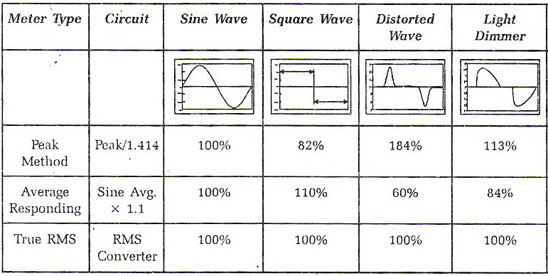
Methods for Measuring Voltages and Currents with Multimeters
The analog meters found on some generator panels will also give erroneous readings when measuring non-sinusoidal currents. Unable to account for the high frequency
harmonic components of distorted waveforms, analog meters tend to indicate values that are lower than the actual values. The presence of voltage and
current transformers in the metering circuit also introduces additional errors in the measurements. To accurately measure waveforms distorted by
harmonics, a meter that will measure the true RMS value is required. True RMS meters overcome these problems by deriving the heating effect of the
waveform to produce an accurate RMS value indication. After all, RMS value represents the heating effect of a voltage or current signal. Early True
RMS meters actually used a thermal detector to measure a heating value. Modern digital meters use instead a digital calculation of the RMS value by
squaring the signal on a sample-by-sample basis, averaging over a period, and then taking the square root of the result.
High Neutral Returns
With incandescent lights (or a Linear Load), if we draw equal current from each leg of our single phase portable generator, there will be no return current on the Neutral.
That is because the Electro Magnetic Fields on the phase legs are polar opposites (180 degrees out of phase), and so cancel one another when combined
on the Neutral return. As illustrated below, the same is true, more or less, for Linear Loads on 3-phase distribution systems.

Linear Loads cancel on the system Neutral
When an inductive or capacitive load causes current and voltage to be out of sync, the phase currents no longer cancel when they return on the neutral. When using magnetic
ballasts, it is normal to have as much as 20-25% of the total amperage return on the neutral when the legs are evenly loaded.
Electronic square wave ballasts, in addition to pulling the voltage and current out of phase, also create harmonic currents that can stack on top of one
another, creating very high currents returning to the power source on the neutral wire. If the nuetral return path has not been oversized to accomodate additinal
current, these high currents can cause excessive heat on the neutral wire, and the neutral bus of the generator. Where the neutral of a distribution system is not fused,
this excessive heat can lead to a possibly hazardous situation. Where high currents
on the neutral can be hazardous, it is important to understand the root cause of these currents so that we can design a location lighting package that
eliminates, or at the very least mitigates, these factors.

The Triplen Harmonics Stack to create excessive current on the Nuetral of a distro system
The harmonic currents produced by electronic HMI ballasts are primarily generated by the diode-capacitor section of the ballast. As you may recall from our
discussion above, the diode-capacitor section rectifies the AC input power into DC, which is then used by the power module to create the square wave. The
diode-capacitor section accomplishes this by first feeding the AC input current through a full wave bridge rectifier, which inverts the negative half of
the AC sine wave and makes it positive. The rectified current then passes into a bank of capacitors which removes the 60 Hz rise and fall and flattens out
the voltage-making it essentially DC. The required DC is then fed from these capacitors to the power module. Since the rectifying circuit of the power supply
only draws current from the AC line during the peaks of the supply voltage waveform, charging the capacitors to the peak of the line voltage, these power
supplies draw current in high amplitude short pulses and pull current out of phase of the voltage. The remaining unused current feeds back into the power stream as harmonic currents.
Of the harmonic currents that electronic ballasts generate, the odd harmonics (i.e. 3rd, 5th, 7th, 9th, etc.) are more of a concern because the even harmonics have
a tendency to still cancel out. Of these the 3rd harmonic, and odd multiples of the 3rd (9th, 15th, etc) are particularly troublesome. These harmonics are called the “triplens.”
What makes them troublesome is that the triplen harmonics dumped back onto each phase of the distribution system are all in phase with each other. For this reason, rather
than cancel each other out on the neutral conductor, as the out of phase fundamentals normally do, they instead add up. By generating harmonic currents that
stack one upon another,
and shifting the phase of the primary currents so that they don't entirely cancel, electronic square wave ballasts can create
unusually high returns on the neutral of the distribution system (see illustration below.) If the lighting package consists entirely of non-linear
light sources without power factor correction, about 80 percent of the current does not cancel out between legs, resulting in very high current on the neutral return.
Return currents of this magnitude can cause sufficient heat to overload the neutral wire, and the neutral bus of the generator, leading
to a possibly hazardous situation since the neutral return has no fused protection.

The Harmonic Currents of Non-Linear Loads do not cancel on the system Neutral
For this reason it is a standard practice when powering large numbers of electronic ballasts on large film sets to size the neutral feeder of the distribution system to carry the sum of the currents of the phase legs times 80 percent (.8). Likewise, the generator is typically oversized to handle the higher return current. However, productions using conventional portable gas generators by necessity, for whom it is not an option to upscale their generator and customize their distribution package for the requirements of a non-linear load, the only alternative is to de-rate the generator and distribution equipment.
Given that there is not much that the end user can do to alter the power output panel of a portable gas generator, all they can do is downsize their lighting package when it consists predominantly of non-linear light sources. The general rule of thumb is to maintain a factor of 3 or 2 to 1 between the continuous rated load capacity of the generator and the total lighting load when it consists of predominantly non-linear light sources. This translates to operating no more than a couple of 1200W HMIs on a 6500W generator if the ballasts are not power factor corrected.
Limit Characteristics & Continuaous Load Ratings
The effects that harmonic currents have on the generators is factored into the rating limits given them. How rating limits are affected by load can be illustrated in a “Limit Characteristic” graph that plots
kVA and kW versus Power Factor. The fluctuations in the kVA line in the illustration below represent the generator’s operating limits depending on whether its load has a leading or lagging Power Factor. It is important to note
that a generator’s Limit Characteristic graph will vary by the type of generator. The illustration below (courtesy of Caterpillar) is for a conventional AVR generator. As we have seen, the power quality of an AVR generator is intractably
linked to its' engine - making the effect of harmonics on the engine's governing systems the primary limiting factor. How the engine and its' governing systems are affected by lagging and leading power factor loads is illustrated by the
engine kW limit line below.
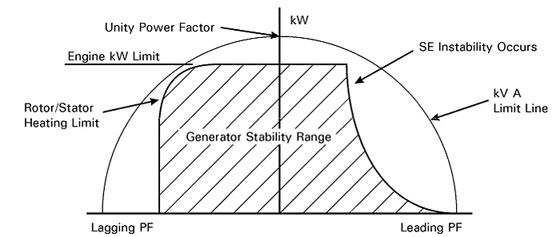
A Limit Characteristic graph for a generator illustrates the effect of leading
or lagging Power Factor on the generator's output.
What this generator’s Limit Characteristic graph tells us is that, operating a capacitive load (the leading power factor quadrant right of the Unity Power Factor center line), this AVR generator first reaches a
thermal limit as a consequence of heat generation in the generator's rotor from harmonic currents. And, since increasing harmonic content leads to a tendency toward erroneous self-excitation (SE), the generator
output is inevitably affected by instability of the Excitation circuit from higher leading power factor loads. Finally, since there comes a point as the
Power Factor of the load decreases, when harmonics inhibit the successful operation of the generator’s Automatic Voltage Regulator all together, and hence the generator’s capacity to generate any power at all, the kW output eventually drops to zero.
This generator’s Limit Characteristic graph also tells us that operating a inductive load with lagging Power Factor (the left quadrant of the Limit Characteristic graph) the generator’s output is more stable; but will
eventually be limited by both the rotor (field) and stator (armature) heating (many times the field temperature limit is lower than the armature limit, especially at low power factor values.)
The limit characteristics of genertors are directly related to the "Continuous Load" rating a manufacturer gives to a generator and explains why two generators that are basically the same will carry different continuous load rating depending on
the market for which they are intended. For example, the typical load a consumer places on a Home Standby generator is Reactive (the computers, microwaves, & fluorescent lighting loads of RVs or Homes), as opposed to the typically Resistive loads
of a construction site (motors, heaters, and incandescent lighting) loads of construction sites. Since, Reactive loads generate harmonic currents that can distort the voltage waveform and can have a severe adverse effect on both the generator and
the equipment operating on it, manufacturers like Honda de-rate the inherent generating capacity of their machines along the curve of its' Limit Characteristic graph - i.e. lowers its' continuous load rating - in order to build in a safety margin
that will allow for the harmonic distortion generated by Reactive Loads (both inductive and capacitive.) In other words, the reason that the same engine and generator components (the gen-set) marketed to the construction trades (the Coleman Model PM0497000)
carries a higher continuous load rating than that marketed for RV Power or Home Standby Power (the Honda EX5500, ES6500, EU6500is, & EM7000is) is that the load that the construction trades put on generators does
not create harmonic currents. Where as, the same gen-set marketed for RV Power or Home Standby Power will carry lower load ratings because the typical load put on it creates harmonic currents and distortion of the power
waveform that can have severe adverse effects on both the generator and the equipment operating on it.
Why Honda would de-rate the load capacity of its' generators intended for markets that use non-linear reactive loads is graphically illustrated in the You-Tube Video
“Compact Fluorescent verses The Generator" discussed previously. In our discussion above, we covered a
number of adverse effects that harmonic noise can have on a generator that will diminish its' power capacity as illutstrated in the Charactistic Limit graph above. To review they include over heating, voltage regulation and speed regulation problems.
Kevan Shaw's You-Tube Video “Compact Fluorescent verses The Generator" demonstrates that the result of these effects on the
operation of a generator can be so severe that they can not possibly be ignored when determining the "Continuous Load" rating of a generator.
If you will recall, when Kevan intentionally "overloads" his 850W two stroke gas generator with a purely reactive load consisting of 30-18W CFL bulbs, he is in fact (because of the
CFL's poor Power Factor of .5) loading the generator with 1120W of Apparent Power. But, because this apparent power load is drawn in short amplitude bursts, it never trips the
breaker on his 850W generator. Instead, the generator simply goes berserk. Where the average user of a portable generator can not distinguish between Resistive and Reactive Loads, manufacturers routinely de-rate the Peak
Load capacity of a gen-set for safety reasons when it will likely operate a predominantly Reactive Load. When, in his demonstration, Kevan turns off the 18W CFL bulbs one at a time until the generator stabilizes with a
Leading Power Factor load of 270 Watts (15 – 18WCFL bulbs), he is in effect doing what generator manufacturer’s do to determine the Peak Load rating of a generator for the RV & Home Standby markets: they determine the maximum
Leading Power Factor load, as compared to Unity Power Factor loads, that a gen-set can reliably operate. What Kevan Shaw finds is that it is not possible to load his generator beyond roughly 65% of it's rated capacity when the
load consists entirely of lights with a poor Leading Power Factor (Max Apparent Power of 540W/850W Generator = .64.)
Reliable operation is only one criterion that manufacturers use to determine a gen-set’s maximum Leading Power Factor load. Another criterion is the effect that continuous exposure to harmonic currents will have on a gen-set.
The overheating of a generator’s wiring and windings as a result of sustained exposure to high Total Harmonic Distortion (THD) levels is an effect of harmonics on generators that manufacturers take into account in
the Continuous Load Ratings (longer than 30 minutes) that they give to generators.
As discussed above, harmonic currents produce heat in several ways. First, harmonic currents can stack on top of one another, creating very high currents returning
to the power source on the neutral wire. If the neutral of the generator has not been oversized to accommodate the additional current, these high currents can
cause excessive heat on the neutral bus of the generator. Second, harmonic currents produce high frequency flux change in the Alternator's Stator core which can
lead to them overheating. Higher core temperatures, in turn, result in higher winding temperatures. Winding heating is, in fact, proportional to effective
or RMS current squared. Rotor loss can also occur because harmonic currents in the Stator will induce currents in the pole faces and windings of the Rotor. And, of course,
harmonic currents cause increased resistive losses everywhere in the generator's electrical distribution, resulting in increased temperatures everywhere, not
only in the Alternator windings.
For these reasons, if a gen-set is intended for a market whose typical load is Reactive (the computers, microwaves, & fluorescent lighting loads of RVs
or Homes), as opposed to Resistive (the motors, heaters, and incandescent lighting loads of construction sites), the manufacturer de-rates the inherent generating
capacity along the downward curve of the Characteristic Limit graph - i.e. lowers the continuous load rating - for that gen-set for that market in order to reduce flux in the Stator core
that leads to heat build up, and eventually to the windings burning out under "normal load." In other words,
the lower Continuous Load rating builds in a safety margin that allows for
the harmonic distortion generated by Reactive Loads (both inductive and capacitive.)
Adverse Effects on Loads
Thus far we have examined the adverse effects on the generator of loads that generate harmonic currents. Now, let us consider the effect that power with a high THD value has upon
the distribution system and the loads operating upon it.
Skin and Proximity Effects
The resistance of a conductor is dependent on the frequency of the current being carried. "Skin Effect" is a phenomenon whereby current tends to flow near the surface of
a conductor where the impedance is least. An analogous phenomenon, "Proximity Effect", is due to the mutual inductance of conductors arranged closely parallel to one another (more on this below.)
Both of these effects are dependent upon conductor size, frequency, resistivity and the permeability of the conductor material.

At fundamental frequencies, the Skin Effect and Proximity Effects are usually negligible, at least for smaller conductors. The associated losses due to
changes in
resistance, however, can increase significantly with frequency. As we saw above, harmonic frequencies are always higher than the 60Hz fundamental
frequency. These higher
frequencies cause electrons to flow toward the outer sides of a conductor. Since the flow of the
electrons is no longer evenly distributed across the cross sectional diameter of the conductor, more electrons are flowing through less copper and
the resistance
of the conductor increases.
Skin Effect

The area of the cross sectional diameter of a conductor used by DC current (left), Low Frequency AC Current (center), High Frequency AC Currents (right).
The graphs below illustrate the difference of varying harmonic numbers on both Proximity Effect and Skin Effect for 12 AWG and 4/0 cable (the cable spacing used to obtain the Proximity Effect values is based on National Electric Code
(NEC)
insulation type THHN.) Comparing the graphs, it is immediately apparent that both Skin Effect and Proximity Effect are more significant in the smaller cable, than the large cable. Within the range of the triplen harmonics alone
(i.e. 3rd, 9th, 15th), both Skin Effect and Proximity Effect increase by 60%.

Which means that the increase in both effects due to harmonics is appreciably more significant in the jacketed multi-conductor cables (10/2 or 12/3) commonly used with small portable generators, than with the
the larger gauge feeder cables (single conductor #2, 2/O, & 4/O) used to distribute power from tow plants.
The increase in resistance due to Skin Effect reduces the ability of stingers (12/3 cable) to carry current, resulting in overheating of the conductors and greater voltage drop over shorter distances than with larger feeder cables.
The greater voltage drop as a result of “Skin Effect” in AC Extension cords can have several adverse effects.

One adverse effect is that it causes equipment connected to the circuit to draw more current to maintain the power rating (watts) of the unit. This, in turn,
can cause protective fuses on electrical boards of equipment to blow - even those of the square wave electronic ballast itself. I experienced this
first hand, when I first tried to operate a 4k HMI Par on a Honda ES6500 (a conventional AVR generator) with the first generation of electronic square wave
ballasts - a Lightmaker. The ballast inexplicably failed when it had never given us problems on mains power. Upon closer inspection back in our shop, we
found that a protective fuse on the main board had failed. We replaced the fuse and continued to operate the ballast off of grid power without incident. But
as soon as we tried to run it again on the Honda the fuse blew. In hindsight, what accounts for the ballast’s erratic behavior was the amount of harmonic
distortion it was feeding back into the power stream. The harmonic currents were not a problem on grid power because they did not induce voltage distortion for the reasons discussed above. But, fed back into the power
stream generated by our Honda ES6500, the same harmonic currents created voltage distortion and sufficient voltage drop from Skin Effect to blow protective fuses on the ballast's boards.
Originally designed to operate large HMIs on DC generators, the first AC/DC Lightmaker ballasts did not incorporate Power Factor Correction or Harmonic Filters. For this reason, when operated on AC power, they fed so much
harmonic distortion back into
the power stream that they were nicknamed Troublemaker ballasts by many set electricians. We discovered the hard way, a design that worked well on DC sources, was not compatiable with small portable AC genrators like
the Hondas for which they were not intended.
Building upon Lightmaker's basic design, manufacturers such as Power Gems, Walker, and Bausch (the manufacturers of Arri's ballasts) incorporated filters to reduce the number of
harmonic currents the ballast feeds back into the power stream. Such improvements led to a second generation of electronic ballasts that operated more reliably on AC
power sources. To reduce the number of harmonic currents generated in the first place, the latest generation of electronic ballasts incorporate Power Factor Correction circuitry (PFC), as well as active line filtration (ALF.) However, since Power
Factor correction is not commonly found in HMI ballasts smaller than 4000W, voltage drop from Skin Effect can still create problems when operating HMI lights on conventional portable generators.
Whenever a piece of electrical equipment inexplicably fails while operating well below its design ratings, and it was operating on the same distribution system as HMIs without power factor correction, it is a safe bet that you will
find blown fuses.
Another common problem associated with Skin Effect is the apparently inexplicable tripping of breakers. Since it is not uncommon to use portable gas
generators to power 1200W HMIs with non power factor corrected electronic square wave ballasts, even a slight increase in load resulting from the voltage
drop caused by Skin Effect can cause what appear to be the inexplicable tripping of circuit breakers in the distribution system or
on the generator. If you recall, a 1200W non-power factor corrected HMI ballast can draw upwards of 19 Amps under normal circumstances (grid power), it doesn’t
take much increase of circuit resistance to push its load over the 20A threshold of distribution circuit breakers. Especially, given that 1200W ballasts are commonly
wired with u-ground Edison plugs rated for 15 Amps, resulting in overheating of the plug end, and an increase of resistance even under normal conditions.
Overheating
As we saw earlier, the harmonic currents generated by non-linear loads provide no useful power to the loads. So where does the energy contained in
these harmonic currents go? Typically it goes into the generation of heat, which can have an adverse effect on the equipment operating on it. The following
is a quick survey of how harmonic currents generate excessive heat in production equipment:
Transformers
Where non-linear loads are prevalent, hot transformers are very common. That is because stray electromagnetic fields created by harmonic currents
induce currents in the windings, core and other structural parts of a transformer. Even under less than full load conditions, a typical distribution
transformer can run surprisingly hot. One reason for this is its’ winding configuration.

(Without a neutral in the Delta Primary harmonic currents circulate continuously in Delta/Wye distribution transformers)
Most distribution transformers we deal with are Delta primary, Wye secondary. The Delta winding has some undesirable characteristics
when significant amounts of harmonic currents are present on the load side. For instance, since a Delta primary does not have a neutral, the induced
currents do not flow through the primary system, and if they are not cancelled, they become trapped in the primary where they continuously circulate
causing extra heating. Called “Eddy Currents”, these currents produce heat that increases substantially at the higher harmonic frequencies. The
relationship is as follows:

(Where:
PEC = Total eddy current losses,
PEC-1 = Eddy current losses at full load based on linear loading only.
Ih = rms current (per unit) at harmonic h
, and h
= harmonic # )
What is significant about the relationship of Eddy Current heat losses as a result of harmonic currents expressed in this equation
is that the harmonic current (Ih) and harmonic number h are squared which means that instead of increasing in a linear fashion they increase exponentially. Put another way the heat generated just doesn’t increase gradually at higher harmonic frequencies, but it jumps drastically.
For linear loads, Eddy Currents are a fairly small component of the overall load losses (typically about 5%). With non-linear loads however, they become a much more significant component, sometimes increasing by as much as 15x to 20x. That is because, as we saw earlier, the 3rd harmonic (and other triplen currents) do not cancel out and so are additive on conductors. Because the stray electromagnetic fields generated by these harmonic currents can add up to be quite substantial, they can induce significant Eddy Currents that continuously circulate in the primary and increase the heating of the transformer core significantly. Where triplen harmonic currents are prevalent, a transformer can easily be subjected to heat losses exceeding its full load rating even though the RMS value of the non-linear load current indicates only partial loading.
Generators
In the windings of a generator’s Stator core, harmonic currents produce high frequency flux change, which can lead to them overheating.
That is because, the windings of generators, like the windings in transformers, over heat in proportion to RMS current squared. In other words,
the heat in a generator’s Stator doesn’t increase gradually when higher harmonic frequencies are present, but it also jumps drastically.
Rotor heat loss can also occur because harmonic currents in the Stator will induce currents in the Rotor pole faces and windings. And as we
saw above, harmonic currents cause increased resistive heat losses everywhere, resulting in increased temperatures everywhere, not only in the windings.
Paralleled Generators
Generators are particularly prone to overheating when used in parallel operation. That is because when generators are paralleled their neutrals are
tied together into a common neutral bus and the differences in the harmonic make up of their voltage waveforms result in current with a large 3rd
harmonic component flowing in the common neutral conductor between the two machines even when there is no load (see below
for more details .) This is referred to as “cross current.”

(Parallel operation of two modified Honda EU6500s can generate 120 Amps of power.)
Cross current can become a problem if triplen harmonics are dumped into the neutral by non-linear loads such as non-power factor
corrected HMIs, Kinos, & LEDs. Because these harmonic currents (the triplens and the 3rd harmonic of the cross current) are in phase with one
another they do not cancel in the neutral as fundamentals do, but instead build one on the other to create elevated cross current with a large
3rd harmonic component. And, since the neutral systems of the two machines are tied together into a common neutral bus, this cross current
circulates continuously between the two generators (as illustrated below).

(With a common neutral bus, cross current circulates continuously between generators operating in parallel)
As was the case with harmonic currents circulating continuously in the Primary of a Delta/Wye transformer, the elevated 3rd harmonic cross current
generates heat exponentially, resulting in the overheating of the neutral conductors and in the case of inverter generators, the inverters as well (see below
for more details .)
Overcurrent Protective Devices (Breakers & Fuses)
The vast majority of low voltage thermal-magnetic type circuit breakers utilize bi-metallic trip mechanisms which respond to the heating effect of the
rms current. In the presence of nonlinear loads, the rms value of current will be higher than for linear loads of the same power. Therefore, unless
the current trip level is adjusted accordingly, the breaker may trip prematurely while carrying nonlinear current. The same is true of early peak-sensing,
electronic-type circuit breakers that respond to the peak value of fundamental current. When carrying harmonic current, this type of breaker may not
operate correctly due to the peak value of nonlinear currents being higher than for respective linear loads. This type of breaker therefore may
trip prematurely at relatively low levels of harmonic current. Circuit breakers are designed to interrupt the current at a zero crossover. On highly distorted supplies which may contain line notching and/or ringing,
spurious “zero crossovers” may cause premature interruption of circuit breakers before they can operate correctly in the event of an overload or fault.
However, in the case of a short circuit current, the magnitude of the harmonic current will be very minor in comparison to the fault current. New designs of electronic breakers include both methods of protection; peak current
detection and rms current sensing. The peak detection method of protection, however, may still trip on relatively low values of peak harmonic current
and trip levels therefore may have to be readjusted accordingly. Similarly, the rms-sensing measures the heating effect of the rms current (as per the
conventional thermal-magnetic type) and may also have to be readjusted to prevent premature tripping on nonlinear loads.
Fuse rupture under overcurrent or short-circuit conditions is based on the heating effect of the rms current according to the respective
i2t characteristic. The higher the rms current, the faster the fuse will operate. On nonlinear loads, the rms current will be higher
than for similarly-rated linear loads, therefore fuse derating may be necessary to prevent premature opening. In addition, fuses at harmonic frequencies, suffer from skin effect and more importantly, proximity effect (see above for details), resulting in non-uniform current distribution across the fuse elements, placing additional thermal stress on the device.
Ground Loops
The significant increase in Proximity Effect in jacketed multi-conductor cable as a result of harmonic currents can lead to the formation of “ground loops.” Current on
neutral conductors with a high THD value will induce voltage in ground wires greater than the 2 volt maximum stipulated by IEEE Standard 1100-1992 "Recommended Practice
for Powering and Grounding Sensitive Electronic Equipment." For instance, there was an episode, recently reported on CML, of a pilot shooting in HD that found they had 50
volts between the shield of the SDI line and ground. In that case the problem was fixed by running a "Drain" wire from the SDI Shield back to the Genny via the electrical
lunchbox at the DIT station. Clearly, if not corrected high neutral-to-ground voltages will cause current to flow on the ground wires and lead to the creation of ground
loops between the tethered components of a HD production package.
A ground loop occurs when there is more than one ground connection path between two pieces of equipment. The duplicate ground paths form the
equivalent of a loop antenna that very efficiently picks up interference currents. Lead resistance transforms these currents into voltage fluctuations. As a consequence of
ground loop induced voltages, the ground reference in the system is no longer a stable potential (a floating ground), so signals ride on the noise. The noise becomes part
of the program signal. The result is that the unwanted signal will be amplified until it is audible and clearly undesirable. Whenever you have current induced on the
grounding system as well as the multiple connections between electronic components that is typical of HD production packages, there is the potential for a "ground loop."
PHOTO COURTESY OF THOMI ENGDAHL

Interference bars caused by induced voltage on ground loop.
Small voltage differences just cause noise to be added to the signals. This can cause an audio hum, interference bars to video signals (above), and transmission errors
in computer networks. Higher currents can cause more serious problems that can damage equipment like sparking in connections and burned wiring. As more and more electronic
components, like lap top computers, hard drives, and HD monitors, are integrated into the typical location HD production package, ground loops become more of a hazard.
RF (Radio Frequency) Interference
If you will recall, the distorted square wave depicted on our scope is in fact comprised of many voltage spikes, at extremely high frequencies, stacking one on top
of the other. That is, if we were to draw out the time base of our scope we would see the square portion of the wave break out into many more voltage "wavelettes" of
a higher amplitude than what we already see in the zig-zag portion of the wave. Each of these high frequency voltage spikes are the result of discreet harmonic currents
being thrown back into the power stream by non-linear lighting loads.
Sprectrum analysis of the high frequency Harmonic Currents making up
a Square Wave that can cause RF Interference
The power stream can become so full of high frequency harmonic currents, that it creates RF
(Radio Frequency) interference. Sensitive electronic devices that are not even hooked up to the distribution system, but simply in close proximity to it, may pick up
the RF (Radio Frequency) interference and begin to show its artifacts, or worse not function at all. Examples of RF interference include lines or fuzzy picture in set
monitors, a buzz in audio tracks, and poor reception in radio mics.
Loads
Thus far we have only discussed the deleterious effect that harmonic currents can have. Voltage harmonics can have just as bad effect on the equipment powered by it. For example, the excess part of a distorted voltage waveform (the shaded area in the diagram below) must be dissipated somehow. This comes in the form of heat. The bigger the current draw from the unit, the more it produces excess heat within the unit that was not factored for in its’ original design.
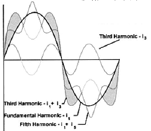
(Unuseable portion of distorted waveform (shaded) dissipated in heat)
Extended exposure to power with harmonic distortion, and the heat it generates, may eventually cause premature component level failures within the unit. Imagine having to replace a new HD field monitor after only a couple of years.
"Inexplicable" Operational Malfunctions
Where there is appreciable voltage waveform distortion created by operating non-linear light sources on a conventional generator, other electrical devices operating on
the same power are unable to use the distorted waveform effectively.
Left: Waveform of grid power.
Right: Waveform of conventional AVR Generator (Honda EX5500) operating non-linear lighting pkg.
consisting of two Arri 1.2kw non-PFC ballasts and a Kino Flo Wall-o-Lite.
For instance, other production equipment that utilizes diode-capacitors and therefore depend on the peak value of the voltage waveform to operate effectively will work sporadically, if at all, on the squared off waveform caused by harmonic currents (above). Like the battery charger operating on a Modified Square Wave Inverter (discussed previously), the Switch Mode Power Supplies (SMPSs) of video cameras, electronic HMI ballasts and Kino Flo ballasts operating on the pseudo square wave of distorted voltage will be starved of power.
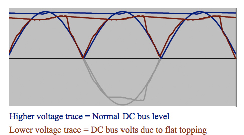
Effect of DC Bus Voltage with Flat Topping
Special precautions must be taken with computers and hard drives. The majority of computer based equipment derives its’ internal DC power from AC power switched by a SMPS, or similar power supply, and so it is often here where harmonic problems first arise. As is evident in the illustration above, voltage flat topping from harmonic currents reduces the operating DC bus voltage these power supplies will generate. As a result, the load will be starved of power even though you may read full line voltage with an RMS meter and the power indicator lights light.
Kevan Shaw’s You-Tube video “Compact Fluorescent verses The Generator" clearly demonstrates this effect. As discussed previously, Kevan Shaw's video (below) demonstrates that, because of
their poor power facgtor, CFL bulbs consume twice the power as the same size incandescent load and generate harmonic currents that adversely effect the governing systems of conventional
AVR generators. A closer analysis of the video also shows that the voltage waveform distortion created by the harmonic currents will also adversely affect electronic equipment operating
on it.
If you will recall, after Kevan has turned off 18W CFL bulbs until the generator has stabilized, he is still "not getting all the lamps to illuminate properly." What accounts for the bulbs not illuminting properly even
though the generator has stablized? While the Harmonic Distortion generated by the remaining CFLs is not sufficient to affect the generator governor, it is clearly affecting the CFLs themselves - an indication that,
short of affecting the generator's governing system, the voltage waveform distortion generated by harmonic currents will adversely effect electronic equipment operating on the distorted power.
Common symptoms are unexplainable operational
malfunctions like computers locking up, tripping breakers, and HMIs not striking or holding their strike. To explain these "inexplicable" operational malfunctions requires a close examination of the characteristic distortion
generated by our various lighting loads. For this reason let us put off that analysis until we look at the waveforms of different lighting loads in the section below titled "Interpreting the Sines."
A Viscious Cycle
As more and more electronic components, like lap top computers, hard drives, and HD monitors, which are themselves sources of harmonic distortion (but of a lower amplitude
than solid state lighting ballasts) are integrated into the typical location production package, harmonic currents begin to combine with unpredictable consequences. In fact,
a viscous cycle can get started. The more harmonic orders that are generated, the more distorted the power supplied by the generator becomes. The more distorted the power
waveform becomes, the more harmonic currents are thrown back into the electrical distribution system, which in turn, creates additional voltage distortion. In this
fashion, something akin to a feedback loop can get started. Very often, the operation of electrical equipment may seem normal, but under a certain combination of conditions, the impact of harmonics is enhanced with unpredictable results.
To summarize, the possible effects that non-linear lighting loads can have on the current waveform reveal themselves in the form of overheating and failing equipment , efficiency losses, circuit breaker trips, excessive current on the neutral wire, interference and instability with generators, noisy or over heating transformers, and service equipment.
Power Factor Correction
The first step in designing a production system that mitigates the problems caused by harmonic currents is to largely eliminate the currents. Where customarily the largest source of harmonic currents in a typical lighting
package are HMI and fluorescent lights, using only ballasts with Power Factor Correction (PFC) circuitry will go a long way in reducing the number of harmonic currents in the power stream. By eliminating the generation
of harmonic currents, a PFC circuit realigns voltage and current and induces a smoother power waveform at the distribution bus. As a result, the ballast uses power more efficiently with minimized return current and
line noise and also reduces heat, thereby increasing their reliability. Where Power Factor Correction in HMI and fluorescent lights offer tremendous benefits in many production applications, but is seldom understood
accurately, let’s explore how it works in more detail.

The effect of Power Factor Correction on the Apparent Power of Arri Electronic Ballasts.
To start, here is a quick summary of what we know of power factor thus far. With a purely resistive “linear load” (Incandescent Lamps, Heaters, etc.) voltage and current waveforms
are in step (or in phase), changing polarity at the same instant in each cycle ( a high power factor or unity.) With “non-linear loads” (magnetic and electronic HMI, fluorescent, & AC LED ballasts) energy “storage” in the loads, impedes the flow of current and results in a time difference between the current and voltage waveforms – they are out of phase (a low power factor.) In other words, during each cycle of the AC voltage, extra energy, in addition to any energy consumed in the load, is temporarily stored in the load, and then returned to the power distribution a fraction of a second later in the cycle. The "ebb and flow" of this nonproductive power increases the current in the line. Thus, a load with a low power factor will use higher currents to transfer a given quantity of real power than a load with a high power factor. The purpose of PFC circuitry is to bring the voltage and current waveforms back in phase (closer to unity power factor.) How this is accomplished depends on whether poor factor is caused by inductive reactance or capacitive reactance. Let us look first at how poor power factor as a result of inductive reactance is corrected in HMI magnetic ballasts.
To understand how Power Factor Correction in magnetic ballasts is accomplished, let’s review what we learned about the operation of magnetic HMI ballasts above. Between the power input and the HMI lamp is a transformer that acts as a choke coil. The transformer provides the start-up charge for the igniter circuit, rapidly increasing the potential between the electrodes of the head’s arc gap until an electrical arc jumps the gap and ignites an electrical arc between the lamp electrodes. The transformer then acts as a choke, regulating current to the lamp to maintain the pulsating arc once the light is burning.
Left: Transformers of a 12k Magnetic HMI Balllast
As you can see in the picture above, the transformers of magnetic HMI ballasts are essentially large coils of wire that are tapped at several places to provide for various input voltages and a high start-up voltage. As such, the transformers of magnetic HMI ballasts exhibit high self-inductance. As we learned above, self-inductance is a particular form of electromagnetic induction characteristic of coils (like those in magnetic HMI ballasts and electric motors) that inhibits the flow of current in the windings of the coil. This opposition to the flow of current is called inductive reactance. In the case of a magnetic HMI ballast, the multiple fine windings of the ballast transformer induces appreciable voltage and considerable current that is in opposition to the primary current, causing the primary current to lag behind voltage, a reduction of current flow, and an inefficiency in the use of power supplied to it. Put simply, the ballast draws more power than it uses to create light.

The Capacitor Bank of a 12k Magnetic Ballast
A common strategy used to correct the self-inductance of transformers in magnetic ballasts (both fluorescent and HMI) is to supply reactive power of the opposite type – i.e. adding capacitors to cancel the high inductance of the transformer’s windings. Power-factor correction capacitors will draw a current with a leading phase angle to offset the lagging current drawn by the ballast transformers. For this reason a bank of capacitor is typically included in the design of magnetic HMI ballasts to bring the current partially back in phase with the voltage. In this sense all magnetic ballasts are power factor corrected.
Since, capacitive reactance distorts the shape of the voltage waveform from a sine wave to some other form (example above), the addition of linear components such as inductors cannot counteract the capacitive reactance of electronic ballasts as the addition of capacitors counteracted the inductive reactance of magnetic HMI ballasts. In the case of electronic ballasts, other more complicated (translate expensive) means of Power Factor Correction is required to smooth out the power waveform.
To understand how Power Factor Correction works in electronic ballasts (HMI, fluorescent, & AC LED) it would help to review what we know about the source of the harmonic currents
that create the high level of capacitive reactance in these ballasts. The harmonic currents produced by electronic ballasts are generated by its’ diode-capacitor section.
As you may recall from our discussion above, the diode-capacitor section rectifies the AC input by first feeding it through a bridge rectifier, which inverts
the negative half of the AC sine wave and makes it positive. The rectified current then passes into one or more conditioning capacitors that remove the 60 Hz rise and fall
and flattens out the voltage - making it essentially DC. The DC is then fed from these capacitors to some type of Switch-mode Converter, that in the case of fluorescent and HMI ballasts, switches it into an
alternating power waveform that excites gases in the lamp. In the case of High Power LEDs, the Switch-mode Converter further conditions the DC power fed to the diode.
Thin Black Trace: Rectifier Bridge converts AC power to rectified sine wave. Thick Black Trace: Stored Capacitor Voltage. Red Trace: Current drawn by capacitors once input voltage is greater than voltage stored in the capacitor (thick black trace.)
Regardless of the type of type of Switch-mode Converter used in the ballast, its’ rectifying circuit only draws current from the AC line during the peaks of the supply voltage waveform. As can be seen in the illustration below, electronic ballasts draw current in high amplitude short pulses. The remaining unused current feeds back into the power stream as harmonic currents.

Voltage and
Current Waveforms generated by Fluorescent ballasts without power factor correction (left)
and with power factor correction (right)
In order to not draw current in high amplitude pulses, and consequently not return unused portions of the power waveform as harmonic currents, the conditioning capacitor(s) must
charge over the entire cycle rather than just a small portion of it. The PFC circuitry of electronic ballasts ( HMI, fluorescent, & AC LED) use some type of multi-stage boost converter typology
to accumulate energy in the capacitor(s) over the entire AC cycle rather than just a brief portion of it.

Voltage and
Current Waveforms generated by High Power AC LED ballasts without power factor correction (left)
and with power factor correction (right)
Now that the capacitor(s) charge throughout the AC cycle rather than just a brief portion of it, the peak current is reduced and harmonic currents are not generated. And, if the
output voltage of the boost converter is set higher than the capacitor(s) input voltage (which is why they are called boost converters), the load is forced to draw current in
phase with the AC main line voltage. In this fashion, the PFC circuit realigns voltage and current and induces a smoother power waveform at the distribution bus. As can be
seen in the comparisons above of the current and voltage waveforms of fluorescent and High Power AC LED ballasts without power factor correction (left)
and with power factor correction (right), PFC circuits can substantially increase power factor (to as much as .98), making ballasts with it near linear loads. As a result, the ballast uses power more efficiently with minimized return current and line noise and also reduces heat, thereby increasing their reliability.

Left: AVR Gen. No-load Waveform. Center: AVR Gen. 1.2KW non-PFC Elec. Ballast Waveform. Right: AVR Gen. 1.2KW PFC Elec. Ballast Waveform.
As the voltage waveform comparisons above demonstrates, a PFC electronic HMI ballast (right) has very little adverse effect on the power waveform of a conventional generator as compared to a non-PFC electronic ballast (center.) If anything it has a positive effect.
For this reason, all major manufacturers include PFC circuitry in large HMIs (12-18kw), and offer PFC circuitry as an option on medium-sized ballasts (2.5-6kw). However, because of the added cost, weight, and complexity of
PFC circuitry, manufacturers have not until recently offered PFC circuitry in HMI ballasts smaller than 2.5kw. Except for one notable exception, when manufacturers do offer PFC circuitry in smaller ballasts it is at a
premium, adding as much as a $1000 to the cost of a 1200W ballast for instance. Ballast manufacturer Power-to-Light, on the other hand, is including PFC circuitry in their ballasts at the same price point as other manufacturer’s non-PFC ballasts.

Power to Light PFC 800W ballast (left) and PFC 1200W ballast (right.)
A typical 1200W power factor corrected electronic HMI ballast has a power factor of .86 which means it will draw 11.5 Amps at 120 Volts to generate 1200 Watts of light (11.5A x 120V= 1380W, 1200W/1380W= .86). While not a huge advantage when plugging into house power, the added efficiency of a PFC 1200 ballast can make a huge difference when powering a lighting package off of a portable generator. For example, when you consider that a Kino Flo Parabeam 400 draws only 2 amps, the 8 Amp difference between using a PFC 1200W electronic ballast and standard non-PFC 1200W electronic ballast, can mean the difference between running four additional Parabeam 400s on a portable generator or not – I think you would have to agree that is a major boost in production capability.
Clearly, the first step in designing a production system that mitigates the problems caused by harmonic currents is to use only Power Factor Corrected ballasts. The next step, as we will see next, is to start with as pure a power waveform as possible.
A Whole New World
Common questions I hear are: Why are harmonics suddenly an issue in motion picture electrical distribution systems? And, why haven’t we needed Power Factor Correction in HMIs until now? To answer these questions, one must appreciate the historical interplay between power generation and load in the past. The lagging power factor (current lags behind voltage) caused by the inductive reactance of magnetic ballasts had a considerably less adverse effect on conventional AVR generators than the leading power factor (current leads voltage) caused by the capacitive reactance of electronic ballasts. That was because Power Factor Correction in the form of capacitor banks brought voltage and current in phase enough that magnetic ballasts operated reliably for the most part; while the type of voltage waveform distortion they generated did not have an adverse effect on the relatively simple linear loads making up production packages of the day (principally the motor drives of film cameras and quartz lighting instruments.)
However, we are no longer in our parent’s linear world. The power generation and electrical distribution systems developed then were not designed to deal with the abundance of non-linear loads like electronic HMI and Kino
Flo ballasts that make up lighting packages today. It’s a problem that has only recently begun because of the increasing use of non-linear lighting loads (for a comprehensive overview see the just released 4th Edition of Harry Box's "Set Lighting Technicians Handbook" - send me a self addressed stamped envelope & I will return it with a discount coupon good for 30% off the 4th Edition through the publisher's website.) The problem is being further compounded by the increasing prevalence
on set of sophisticated electronic production equipment like HD cameras, computers, hard drives, and monitors which are not only sensitive to harmonic distortion, but are themselves sources of harmonic distortion.
For instance, the self-excited AVR systems of conventional generators were not designed to operate with leading power factor loads. If you will recall from our
previous discussion, in AVR systems the AC voltage generated is controlled by DC excitation of the electro-magnets of the generator's Rotor. The amount of DC
excitation required is a function of generator load; or, put another way, the excitation required to maintain constant voltage increases with load. The type
of load also affects the amount of excitation required. Lagging power factor loads (magnetic ballasts) require more excitation than a unity power factor load
(Quartz Lights.) Leading power factor loads (electronic ballasts) require less excitation than unity power factor loads.
Rudimentary AVR systems like those in portable generators are ill equipped to deal with leading power factor loads like electronic ballasts because the harmonic currents
they generate create flux in the armature coils of the Stator that reacts
additively with the Exciter flux in the field poles of the Rotor to increase saturation and produce a higher terminal voltage than called for a given load. Consequently, the AVR system
responds erroneously to control voltage by reducing excitation. The end result is that the regulator goes to its minimum excitation capability while the additive
excitation of the armature flux from the leading power factor causes the terminal voltage to continue to rise and not be controlled by the voltage regulator.
Erroneous regulation of voltage is just one example of the more severe effect that leading power factor loads have on conventional AVR generators than do lagging power factor loads. In the next section, where we compare the characteristic voltage waveform distortion created by different lighting loads on different generators, we will see that leading power factor loads also have a more severe effect on other production equipment operating on the same power. And, that
after partial Power Factor Correction with capacitors, the lagging power factor of magnetic ballasts can actually have a positive effect on the already distorted power waveform of conventional AVR generators like the Honda EX5500. For these reasons, as long as you could shoot at one of the safe “flicker free” frame rates, magnetic ballasts worked reasonably well on conventional AVR generators with frequency governors until the introduction of electronic square wave HMI ballasts.
When electronic square wave HMI ballasts came on the market, they were at first thought to be the solution to all the problems inherent in running HMI lights on small portable generators. Since they are not frequency dependent, it was thought at first that electronic square wave ballasts would operate HMIs more reliably on small portable generators – even those without frequency governors. By eliminating the flicker problem associated with magnetic ballasts, they also eliminated the need for the expensive AC governors required for flicker free filming with magnetic HMI ballasts and portable gas generators.
For these reasons, as soon as electronic square wave ballasts appeared on the market, many lighting rental houses replaced the expensive crystal governed Honda EX5500 with the less expensive non-synchronous Honda ES6500. The theory was that an electronic square wave ballast would operate reliably on a non governed generator and allow filming at any frame rate, where as a magnetic HMI ballast operating on an AC governed generator allowed filming only at permitted frame rates. In practice, electronic square wave ballasts turned out to be a mixed blessing. As we have seen in this section, the leading power factor caused by the capacitive reactance of the new electronic ballasts proved to have a more severe effect on conventional AVR generators than did the old magnetic ballasts.
Since magnetic ballasts worked reasonably well on AVR generators with governors, in the past, attention was only given to portable generator features such as automatic voltage regulation, speed regulation and AC Frequency. But, given the increasing prevalence of leading power factor loads and the problems they cause, an increasingly more important feature today is the quality of the generated waveform and the impedance of the power system. For this reason, it is imperative that today’s power generation and electrical distribution systems be designed for non-linear lighting loads, not just linear lighting loads. This is especially true of the systems to be used in low budget independent production because these productions have traditionally relied upon portable gas generators that are more susceptible to the adverse effects of harmonic distortion. These productions are also increasingly embracing the use of HD digital cinema production tools, like inexpensive HD camcorders, laptop computers and hard drives, that require cleaner and more reliable power on set to operate effectively.
__________________________________________________________________
Interpreting the Sines
As we learned above, the magnitude of the current and voltage waveform distortion depends upon the quality of the original applied power waveform and the relative size
of the nonlinear loads with respect to the source impedance and capacity of the power generating system. That is, the amount of voltage distortion increases as distortion
of the applied waveform increases and the percentage of nonlinear loads taking up the total capacity of the power generating system increases. For this reason, when
designing a better production system, it is worth looking at the specific magnitude and order of the harmonics generated by each type of lighting load on each type of power supply (Grid, Conventional AVR Generators, Inverter
Generators.) A thorough understanding of the interaction between these elements will enable us to design a produciton system capable of providing cleaner and more stable
power. To that end, I ran a series of tests in order to analyze the interaction of conventional AVR generators with AC
Frequency Governors (a Honda EX5500 with Governor), as well as inverter generators (a Honda EU6500is), with the prevalent linear and non-linear light sources.
The Test Set Up

Left: Honda EU6500is (L) Honda EX5500 (R) Center: Test Set-Up w/60A Full Power Transformer. Right: P@L PFC 1200W Elec. Ballast (L), Arri Non-PFC 1200W Elec. Ballast (C), Arri 1200W Magnetic Ballast (R)
The test consisted of running different loads (quartz, kino, mag HMI, non-PFC HMI, PFC HMI) on each generator and grid power as a sort of control. I then took
pictures of the resulting waveform on an oscilloscope. I have attached the side by side comparisons for each load type. The frame on the far
left is always grid power (our control), the center frame is always the EX5500 power, the right frame is always the EU6500is power as measured at the power bus.
They appear in the following order: no-load, 2k Open Face Quartz Light, Arri 1200 Par Plus with Magnetic Ballast, the same Arri 1200 Par Plus with a non-PFC electronic
ballast, the same Arri 1200 Par Plus but with a Power-to-Light 1200 PFC ballast, and finally a Kino Flo 4'-10 tube Wall-o-Lite fixture.
Voltage Waveforms
No Load Waveforms

Left: Grid Power w/ no load. Center: Conventional AVR Power w/ no load. Right: Inverter Power w/ no load.
As one would expect the wave form of the grid power is a nice sinusoidal waveform and has a Total Harmonic Distortion (THD) in this case of less than 3%. The waveform of the EX5500 exhibits the less sinusoidal waveform, with a THD of 17%, that is typical of conventional AVR generators. The waveform of the power generated by the EU6500is is, as Honda claims, a true sinusoidal waveform with a THD of 2.5%. The power generated by the EU6500is is in fact cleaner than the grid power coming out of our wall outlet.
Incandescent Lights (Resistive Linear Loads)

Left: Grid Power w/ 2K Open. Center: Conventional AVR Power w/ 2K Open. Right: Inverter Power w/ 2K Open.
As a purely resistive load our Mole 2k Mighty open face has very little adverse effect on the respective waveforms. If anything it has a positive effect on the Honda EX5500.
The result confirms what every electrician knows first hand from operating these machines. Namely, that they run smoother under load and that fact is reflected in the
smoother power waveform under load than without a load.
Unfortunately, incandescent lights are the least efficient light sources of the three that we are testing here. Since eighty percent of the energy consumed by an incandescent light goes into the generation of heat, they generate less lumens per watt of any other light source. Add to that, the fact that the Full CTB gel required to convert incandescent lights to daylight has a transmission factor around .3 (it takes a 1000 Watt incandescent source to generate 300 Watts of day light balanced light) make them the most impractical light source for daylight fill or the creation of cool moonlight.
As near a pure linear load as we will find, incandescent lights interact well with small portable generators. However, their inefficiency make them a poor choice when power is limited.
Magnetic HMI Ballasts (Inductive Non-linear Load)

Left: Grid Power w/ 1.2Kw Arri Magnetic Ballast. Center: Conventional AVR Power w/ 1.2Kw Arri Magnetic Ballast. Right: Inverter Power w/ 1.2Kw Arri Magnetic Ballast.
What we see within the inverter power waveform (right) is a spike in the voltage generated by current created by the self-inductance of the coils inside the ballast’s transformer. If you will recall from our discussion of magnetic ballasts above, an opposing current is induced in a current-carrying wire within a coil when the principle current changes as it alternates. Since the opposing current is induced after the voltage peaks and begins to descend again, the induced current lags the voltage and pulls the primary current out of phase with the voltage so that it lags behind the voltage. When it encounters an impedance, this opposing current induces voltage that appears as a spike in the oscilloscope waveform.
Harmonic currents of this magnitude can cause false circuit breaker tripping. For instance, when running multiple magnetic ballasts, these harmonic currents can stack and induce peak voltage values many times higher than the power waveform. Under such circumstances, peak sensing circuit breakers will trip even though their amperage value has not been exceeded.
Voltage spikes, as a result of stacking harmonic currents, goes a long way toward explaining this nightmare scenario: a number of years ago, I was gaffing a night shoot for American Experience with a 25KVA Mulitquip Silent Star generator and we had problems with breakers on our HMIs tripping intermittently. We put a handheld scope meter on the power line and there was harmonic distortion from the magnetic ballasts that we were using, but not so much that I thought would be a problem for a 25KVA (180A) generator. Throughout the night, each time an HMI went out unexpectedly in the middle of a shot, we eliminated one in our set up until we found a happy medium of a couple of babies, a 1200 Par and a 2500 Fresnel – much less than I would have expected a generator of that size could run reliably. I learned that hellish night that there are no hard and fast equations to determine how many magnetic HMIs you can safely run on a generator. The harmonics of ballast noise react in unpredictable ways.
Non Power Factor Corrected Electronic HMI Ballasts (Capacitve Non-linear load)

Left: Grid Power w/ 1.2Kw Arri non-PFC Elec. Ballast. Center: Conventional AVR Power w/ 1.2Kw Arri non-PFC Elec. Ballast. Right: Inverter Power w/ 1.2Kw Arri non-PFC Elec. Ballast.
The first thing to note is that the noise fed back into the distribution system by the electronic ballast creates harmonic distortion in the power generated by
both generators where it has no adverse effect on the grid power. The reason for this is that the magnitude of voltage waveform distortion is a function of the source
impedance and the relative size of the nonlinear load with respect to the capacity of the power generating system. As we see in the frame on the left, an HMI
light with non-PFC electronic ballast operating on a wall outlet will not produce voltage distortions because the impedance of the electrical path from the power plant to
the light is so low, the distortion of the original voltage waveform so small (less than 3%), and the plant capacity so
large, that loads placed upon it will not effect the voltage at the load bus.
However, as we see in the center and right frames, it is an all together different situation when plugging a 1200W non-PFC HMI ballast into a small portable generator. Where,
in this case, the sub-transient impedance of the generators are higher, and the percentage of the capacity of the generator that the non-linear electronic ballast takes up is
relatively high, current distortion from the harmonics created by the electronic ballast produces voltage distortion. These frames clearly demonstrate that the electrical artifacts
generated by electronic ballasts are amplified on small generators where they are not on grid power.

Even though RMS voltage remains the same, the Peak Value drops
as a result of squaring of waveform from harmonic currents
The second thing worth noting is the type of voltage distortion created by the 1200 Watt non-PFC electronic ballast in the power of both generators. Since, according to Ohm’s Law
current reacts with impedance to cause voltage drop, in the case of capacitive non-linear loads like electronic ballasts that consume current only at the
peak of the voltage waveform (to charge their smoothing capacitor/s), voltage drop occurs only at the peak of the voltage waveform -
causing the “Flat Topping” we see in the oscilloscope shots above that is characteristic of this type of load. In other words, since electronic ballasts consume current only at the
peak of the voltage waveform, voltage drop due to system impedance occurs only at the peak of the voltage waveform. This explains why the
harmonic currents fed back into the distribution system by the electronic ballast has the effect of squaring off the voltage waveforms of the power generated by both types of
generators.

Left: Conventional AVR Generator w/1200W non-pfc electronic ballast. Right: Inverter Generator w/1200W non-pfc electronic ballast
A third thing worth noting is that the artifacts of harmonic distortion are amplified to a lesser degree in the inverter generated power (above right) than the non-inverter power (above left). Possible explanations for this are, as we saw above, the original waveform of the power generated by the EU6500is (our inverter generator) has less harmonic distortion at the outset than that originally generated by the EX5500 (our conventional AVR generator.) Another possible explanation is that the sub-transient impedance of inverter generators is appreciably less than that of conventional AVR generators. As discussed at the outset, in the case of inverter generators, voltage and frequency are independent of the engine. As a consequence inverter generators have very low internal reactance to changes in load. And, as discussed above, the generator with the lowest internal reactance to an instantaneous current change at a given load (impedance) will typically have the lowest value of total harmonic distortion under nonlinear load conditions (more on this latter.)
Voltage notching at the zero cross over is an indication of
high frequency “wavelettes” within the primary sine wave.
A fourth thing to note is the character of the greater voltage distortion created by the 1200 Watt non-PFC electronic ballast in the power generated by the conventional generator
(EX5500.) As discussed above, each harmonic current in an electrical distribution system will cause a voltage at the same harmonic to exist when the harmonic current flows into
an impedance. In other words, the higher the system impedance the more likely harmonic currents will induce voltage at the same frequencies. These voltage harmonics appear in the
oscilloscope shot above as a zig-zag saw tooth pattern. This pattern does not appear in the voltage waveform of the inverter generator because of its’ much lower impedance. Once again,
we see that the generator with the lowest internal reactance to an instantaneous current change at a given load (impedance) will have the lowest value of total harmonic distortion under nonlinear load conditions.
Harmonics making up a Square Wave.
The zig-zag saw tooth pattern above is also an indication that a square voltage waveform is created by not just the primary current creating a voltage drop when it encounters system impedance, but in fact by many many
harmonic currents, at extremely high frequencies, also creating voltage drop as they also induce voltages at the same frequencies. Put another way, the square wave depicted on our scope is in fact comprised of many, many
voltage spikes, at extremely high frequencies, stacking one on top of the other. Harmonic currents at these frequencies can create RF (Radio Frequency) interference in sensitive electronic devices in close proximity to
it. Examples of RF interference include lines or fuzzy picture in set monitors, a buzz in audio tracks, and poor reception in radio mics.

Inverter Generator w/1200W non-pfc electronic ballast
In the case of the Inverter Generator (EU6500is), even though the same harmonic currents are fed back into the distribution system by the electronic ballast, because of its’ lower
system impedance and purer original power waveform, it retains an over all sinusoidal shape. The shape of its’ waveform is such that electrical devices that are dependent on peak
values may still operate effectively. It also exhibits much less severe distortion as a result of high frequency harmonic currents. The appreciable difference in voltage distortion
created here by the same light demonstrates that an inverter generator will provide cleaner power regardless of the type of load. Not only will a non-PFC electronic ballast have
fewer adverse effects on other equipment when operating on an inverter generator, it will operate more reliably as well (more on this when we look at the effect of multiple non-linear loads below.)
Power Factor Corrected Electronic HMI Ballasts (Capacitive Near Linear Load)
Because of the problems we have seen above, ballast manufacturers incorporate Power Factor Correction (PFC) circuits into their large electronic HMI ballasts (6-18kw)
by necessity. As discussed, a PFC circuit realigns voltage and current and induces a smoother waveform. As a result, the ballast uses power more efficiently with minimized return
current and line noise. Less heat is generated so the ballast operates more reliability.

Left: Grid Power w/ 1.2Kw P-2-L PFC Elec. Ballast. Center: Conventional AVR Power w/ 1.2Kw P-2-L PFC Elec. Ballast. Right: Inverter Power w/ 1.2Kw P-2-L PFC Elec. Ballast.
A quick look at the waveform comparison confirms these characteristics of power factor corrected HMI ballasts. A near linear load, the PFC electronic ballasts tested here has
no adverse effect on the respective waveforms. If anything, like the purely resistive load of the 2k incandescent light, it has a positive effect on the Honda EX5500. The
generator runs smoother under the PFC load than without a load. That fact is reflected in the smoother power waveform under load.
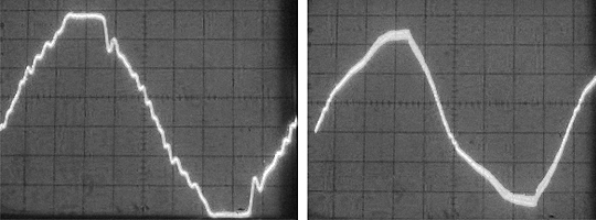
Left: AVR Generator No-Load
Right: AVR Generator with PFC Electronic HMI Ballast
Note the positive effect that
the near-linear load has on the power from a conventional AVR generator.
It is also worth noting that since PFC electronic ballasts have no adverse effect on power, the power generated by the inverter generator (EU6500is) retains its near perfect sinusoidal
waveform. For this reason, sensitive electronic equipment running on the same power will operate reliably and effectively.
All major manufacturers include power factor correction on large HMIs (6-18kw) because the heat and noise reduction is absolutely necessary for their reliable operation. However, because of the
added cost, weight, and complexity of PFC, manufacturers offer PFC as an option on medium-sized ballasts (2.5-4kw) and have not until recently offered PFC on HMI ballasts smaller than 1.2kw.
What sets the Power-to-Light (P2L) HMI Ballast product line apart from others is that P2L is incorporating Power Factor Correction (PFC) into their 800w, 1200w, 2.5kw/4kw ballasts at the same
price points as other manufacturer’s conventional non-PFC electronic ballasts.
Electronic Fluorescents Ballasts (Capacitve Non-linear Load)
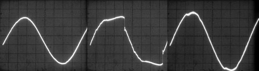
Left: Grid Power w/ Kino Flo Wall-o-Lite. Center: Conventional AVR Power w/ Kino Flo Wall-o-Lite. Right: Inverter Power w/ Kino Flo Wall-o-Lite.
The first thing to note is that with a power factor around .6 the older style electronic ballasts of the Kino Flo Wall-o-Lite do return some harmonic currents to the power
stream that
distort the power waveforms of the generators – but to a much lesser degree than a non-PFC electronic HMI ballast. The second thing to note is that the distortion of the
voltage waveform is considerably less in the case of the inverter power (far right) than that of the conventional generator (center.) The reason for this is that, as
we saw above, the original waveform of the power generated by the EU6500is (our inverter generator) has less harmonic distortion at the outset than that originally
generated by the EX5500 (our conventional AVR generator.) Where the harmonic distortion of the power generated by the inverter generator is on par with the grid power,
what little voltage distortion there is comes as a result of the generator’s high sub-transient impedance.
Given how well Kino Flo ballasts interact with inverter generators, not to mention their versatility (they can operate both 5500K & 3200K lamps) and their efficiency
(they consume 1/10 the power of comparable incandescent soft lights), Kino Flo lights would appear to be an ideal light source to operate off of portable inverter
generators, and hence a good candidate for our better production system, except for one drawback. Fluorescent lights have a very broad soft light output that is hard to
control. The light also tends to drop off rapidly which means that to serve as key sources, the units need to be positioned close to the subject they are lighting. These
characteristics make them best suited to be fill sources in dramatic productions. They are really only suited to serve as key sources in documentary interview set ups where the keys are typically positioned close to the interview subject. In that capacity they generate a wonderful
soft light that wraps around the interview subject without wilting them. Given these characteristics, fluorescent lights in the past had only limited applications in
set lighting until the development by Kino Flo of their ParaBeam fixtures (see below for more details.)
__________________________________________________________________
The Effects of Multiple Non-Linear Loads
Thus far we have looked at the effect of just one 1200W non-pfc electronic ballast on 5500W & 6500W generators. What would be the accumulative effect of multiple non-linear loads on a generator? To see, I ran a package consisting of two Arri 1200 Par Pluses with non-pfc electronic ballasts, as well as a Kino Flo 4’ – 10 tube
Wall-o-Lite on the EX5500 (our conventional AVR generator). And for the sake of comparison, I ran the same package but with power factor corrected electronic HMI ballasts on the EU6500is (our inverter generator.) The difference between the resulting waveforms is startling.
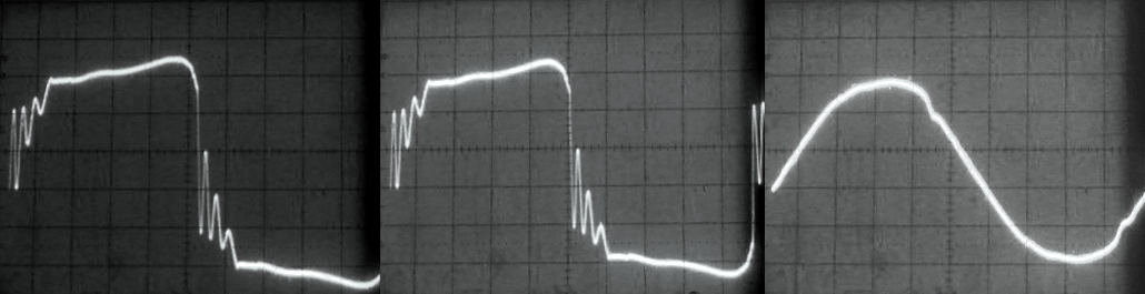
Left: Conventional AVR Power w/ Pkg. of non-PFC Elec. Ballasts & Kino Flo Wall-o-Lite. Center: Scope time base adjusted to bring elongated
waveform back on screen. Right: Inverter Power w/ Pkg. of non-PFC Elec. Ballasts & Kino Flo Wall-o-Lite.
The waveform on the left is no longer grid power but the power of the EX5500 distorted by the noise generated by multiple non-PFC HMI & Kino electronic
ballasts. As we would expect, since the percentage of the total capacity of the generator taken up by non-linear loads has increased, the amount of voltage
distortion in the power generated by the conventional AVR generator (the EX5500) has increased as well. The first artifact of the higher Total Harmonic
Distortion (THD) we notice is that the entire waveform is elongated such that it no longer fits on the oscilloscope display. The center frame is the scope
adjusted so that the entire waveform fits on its screen. The elongation of the waveform indicates that, despite the regulation of its engine speed by the
Barber Coleman AC Frequency governor, the greater load of non-PFC electronic ballasts has caused the generator to slow down slightly. As you would expect with a conventional AVR generator like the EX5500, the drop in RPMs results in a shift in the frequency (HZ) of the AC power waveform. The AC Frequency of the inverter generator, on the other hand, is unchanged by the additional non-linear load.

Left: Effect of harmonics of one non-pfc 1200W Electronic Ballast.
Right: Effect of stacked harmonics of two non-pfc 1200W Electronic ballasts
and solid-state ballast of Kino Flo Wall-o-Lite
The slow down of the EX5500 (our conventional AVR generator) might be attributable to the second artifact of the higher THD we notice - the amplitude of the high frequency “wavelettes” within the primary sine wave (the zig-zag saw tooth pattern) has also increased. The high voltage notching and heavy ringing transients present in the more
distorted waveform (above) is creating multiple zero-crossings within one cycle of the AC waveform. Since, the Barber Coleman engine governor used in this particular Honda EX5500 uses a
speed reference signal obtained by sensing the zero-crossings of the frequency of the output voltage inside the AVR unit, the multiple zero-crossings may be confusing the governor unit,
causing it to regulate the engine at the wrong speed.
There was a similar case reported on the Cinematographer’s Mailing List (CML.) It involved a Honda EX5500 equipped with a Barber Coleman governor. The EX5500 also had a digital frequency meter installed on the front panel. As reported in the post, the digital meter worked fine with tungsten lights. But, as soon as a 1200 Par was struck the digital meter read 120Hz rather than 60Hz. The gaffer knew the meter was malfunctioning, and not the governor. In order, to generate 120Hz power, the generator would have to run 7200 rpm and the pitch of the engine had not changed. When the gaffer metered the frequency of the generator is was slightly off, but they were not too concerned because they were using flicker free electronic ballasts
and there was no problem visible in the monitor or on playback. However as soon they tried to run a second 1200 Par the engine began heaving. The lights continued to run without visible flicker; but, a lap top that was being used to check the download of footage to the hard drive locked up. When generator power was metered again, the Hz was cycling over a wide range. If one of the 1200 pars was turned off, the frequency would become stable again.
Clearly the harmonic noise generated by the electronic ballasts was the problem in this case. The higher voltage notching and heavier ringing transients were creating multiple zero crossings and throwing the governor off speed.

Left: Effect of harmonics of one non-pfc 1200W Electronic Ballast.
Right: Effect of stacked harmonics of two non-pfc 1200W Electronic ballasts
and solid-state ballast of Kino Flo Wall-o-Lite
Also of note in the waveforms above is that the peak voltage has dropped even further, and the duration of the flat plateau is extended. Where there is appreciable voltage waveform distortion of this type, created by operating capacitive non-linear light sources on a conventional generator, other electrical devices operating on the same power may be unable to use this distorted “pseudo square wave” effectively. For instance, other production equipment that utilizes diode-capacitors and therefore depend on the peak value of the voltage waveform to operate effectively will work harder, if at all, on the squared off waveform caused by harmonic currents (above).
Most electronic production equipment in use today utilizes AC-to-DC diode-capacitor power conversion circuits in one way or another. As discussed
at length above, HMI and Fluorescent electronic ballasts utilize them to convert AC input power to DC power so that a Switch-mode Converter can
convert the DC power back to an alternating power waveform that ignites the lamp (50/60Hz Square wave in the case of HMIs and high frequency
sine wave in the case of Fluorescent ballasts.) The AC power supplies of lap top computers and video cameras, as well as DC battery chargers,
also use diode-capacitors to convert AC-to-DC. But, instead of using a Switch-mode Converter to switch the DC back to AC, they use power
conditioning components to supply DC power of a prescribed voltage. Regardless of the type of power (AC or DC) ultimately generated, what is
important to realize is that all diode-capacitor power conversion circuits place the load on the peaks of the supply AC. Given this fact, what effect would a highly distorted voltage waveform with peak voltage drop have
upon them? To see, lets first review what we know about how diode-capacitor circuits operate.

Step 1: Rectifier Bridge converts line frequency AC power to rectified sine wave.
Step 2: rectified sine wave is flattened to DC by conditioning Capacitor.
If you will recall from our discussion of electronic ballasts, the diode-capacitor section converts the AC power to DC power by first feeding the
AC input through a bridge rectifier, which inverts the negative half of the AC sine wave and makes it positive. The rectified current
then passes into a conditioning capacitor/s that removes the 60 Hz rise and fall and flattens out the voltage - making it DC.
Yellow Trace: Rectifier Bridge converts AC power to rectified sine wave. Blue Trace: Stored Capacitor Voltage. Red Trace: Current drawn by capacitors once input voltage is greater than voltage stored in the capacitor (Blue trace.)
As shown in the illustration above, the diode-capacitor circuit only draws current during the peaks of the supply voltage waveform as it charges the conditioning capacitor to the peak of the line voltage.
Since the conditioning capacitor can only charge when input voltage is greater than its stored voltage, the capacitor charges for a very brief period of the overall cycle time. Since, during this very brief
charging period, the capacitor must be fully charged, large pulses of current are drawn for short durations. Consequently, all diode-capacitor circuits draw current in high amplitude short pulses that roughly
coincide with the peak of the voltage waveform.

A pseudo square wave after being rectified by a full bridge rectifier
Based upon how diode-capacitor circuits operate, what effect would a "flat topped" voltage waveform exhibiting peak voltage drop (like the one pictured above) have upon loads, like lap tops, camera power
supplies and battery chargers, that also utilize SMPSs? If we compare one half
cycle of a rectified sine wave to one half cycle of the distorted pseudo square wave generated by just one non-pfc 1200W electronic ballast,
we see that one consequence is that the period during which the capacitors of their SMPSs must recharge is appreciably shortened. Given a shorter interval to
charge, the capacitor/s will draw current in even higher amplitude shorter bursts. The diode-capacitor circuit therefore works harder, drawing more current during an even briefer charging period, reducing its power
factor and increasing its apparent power or load. As a consequence protective circuit breakers may trip or fuses blow.

Left: half cycle of rectified sine wave. Right: half cycle of rectified pseudo square wave.
Blue Line: Minimum Capacitor Voltage. Red Lines denote interval during which current
will be drawn by capacitors once input voltage is greater than voltage stored in the capacitor.
Another adverse effect is that more harmonic currents are generated as less of the power waveform is used by the circuit. In fact, a viscous
cycle can get started. The more harmonic currents that are generated, the more distorted the power supplied by the generator becomes. The more
distorted the power waveform becomes, the more harmonic currents are generated. In this fashion, something akin to a feedback loop can get started
until the effect of the harmonics is enhanced to the point where equipment stops working all together.

Blue Line: Minimum Capacitor Voltage. Red Lines denote interval during which current will be drawn
by capacitors once input voltage is greater than voltage stored in the capacitor.
To see why this might happen we have only to compare the pseudo square wave created by the single non-PFC 1200W electronic HMI ballast to that
created by the 2500W package of non-PFC electronic HMI and Kino ballasts above. Based upon our discussion of how diode-capacitor circuits operate,
we can see in the oscilloscope shot on the right that the peak value of the psuedo square wave created by the 2500W package (after it has be rectified)
may not reach a sufficient level to charge the capacitor/s of a power supply. Whether the ballast of a light, or the AC power supply of a lap top,
the equipment may be starved of power even though its’ power indicator lights up, and a true RMS voltmeter would indicate about 120 volts on the line.
Common symptoms of power starvation are computers locking up, breakers tripping, and HMIs not striking or holding their strike. And, where now more of
the distorted wave falls outside a sinusoidal waveform, more excess heat will be generated in its' electrical components causing them to overheat and eventually burn up.
Unuseable portion of distorted waveform (shaded) dissipated in heat.
The magnitude of THD we see here, created by the harmonics of multiple non-PFC electronic ballasts stacking in our distribution system, goes a long way toward explaining this recent scenario: a local broadcast rental house sent several
non-linear editing systems to the Iron Man Triathlon for field editing. The laptops kept inexplicably locking up until their power supply was changed from a generator that was also supplying a large number of HMIs to the onboard generator
of the satellite truck. Once they were moved from the highly distorted power supply of the lighting generator to the highly refined power supply of the satellite truck the laptops operated flawlessly.
Same as Above Left: Conventional AVR Power w/ Pkg. of non-PFC Elec. Ballasts & Kino Flo Wall-o-Lite. Center: Scope time base adjusted to
bring elongated waveform back on screen. Right: Inverter Power w/ Pkg. of non-PFC Elec. Ballasts & Kino Flo Wall-o-Lite.
The third frame on the right, is the same package of lights but with power factor corrected electronic HMI ballasts on the EU6500is (our inverter generator.)
As you can see, the difference between the resulting waveforms is startling. Even though we are running the same overall load in terms of watts, the fact
that the ballasts are power factor corrected, that the power generated by the inverter generator has very little inherent harmonic distortion
(less than 2.5%), and that the system impedance is very low, results in virtually no voltage waveform distortion of the power running through the distribution system. For this reason, sensitive
electronic equipment running on the same power will continue to operate reliably and effectively without damage even though the overall load on the
generator has increased. These frames clearly demonstrate that it is essential to have PFC circuitry in your ballasts, and to operate them on an inverter
generator, when your load consists primarily of HMIs and Kinos.
What it all Means
From the results of these tests the outline of a better production system is beginning to take shape. If there is one conclusion to be drawn from these tests, it is that when your lighting package
consists predominantly of non-linear light sources (HMI, Fluorescent & LED lights) it is essential to have PFC circuitry in the power supplies and to operate them on an inverter generator. The
combination of improved power factor and the nearly pure power waveform of the inverter generator makes it possible to power larger lights, or more smaller lights, than has ever been possible
before on a small portable gas generator.

Left: Power waveform distorted by Non-PFC 1200W HMI ballasts on conventional generator.
Right: Near perfect power waveform of the same lights with PFC ballasts on inverter generator.
In the past, the primary factors limiting the use of non-linear light sources on portable generators have been their inefficient use of power and the harmonic noise they throw back into the
power stream (above left.) However, with the recent incorporation of PFC circuitry in electronic HMI ballasts smaller than 4kw and the introduction of inverter generators, it
is now possible to generate clean stable set power (above right) capable of operating larger lights (HMIs up to 6kw or Quartz lights up to 5kw), or more smaller lights, off of portable gas
generators than has ever been possible before.
The Limit Characteristic graph for a conventional AVR generator.
Note the diminishing effect that leading Power Factor loads have on the generator's power capacity (illustration courtesy of Caterpillar.)
That is, where the harmonic distortion created by non-PFC power supplies reacting poorly with the distorted power waveform of conventional AVR generators (illustrated in the Limit Characteristic graph above), limited the number of non-linear light sources
you could use to roughly half (65%) of the generators capacity. An inverter generator can be loaded to capacity with PFC HMI, Fluorescent, and LED power supplies because the near-linear nature of the
load and the extremely low harmonic distortion (less than 2.5%) of the original AC power waveform of inverter generators results in virtually no distortion of the power waveform.

The Limit Characteristic graph for an Inverter generator.
Note the negligible effect that leading Power Factor loads have on the generator's power capacity.
What this means is that, as illustrated in the Limit Characteristic graph above, you can safely power bigger lights, or more smaller lights, on a portable gas generator than was ever possible before. For
example, where a
Kino Flo ParaBeam 400 draws only 2 amps, the 8 Amp difference between using a PFC 1200W electronic ballast and non-PFC 1200W electronic ballasts, can mean the
difference between running four additional ParaBeam 400s on a portable generator or not. Given this new math, when you add up the incremental savings in power to be gained by using only PFC HMI ballasts, add to it energy efficient sources
like Kino Flos, and combine it with the pure waveform of inverter generators, you have what, I would argue, amounts to a paradigm shift in lighting with small portable generators.
Where before you could not operate more than a couple 1200W HMIs on a conventional AVR generator, now you can run a lighting package consisting of PFC 2.5kw, 1200, and 800 Watt HMI Pars, a couple of Kino Flo ParaBeam 400s, ParaBeam 200s, and a Kino Flo FlatHead 80 off of a Honda EU6500is Inverter Generator with the aid of a 60A Full Power Transformer/Distro. Given the light sensitivity of HD Camcorders, this constitutes a complete location lighting package for HD Digital Cinema productions.
Sizing Portable Generators
Sizing a portable generator for a lighting load can be very complicated. As we have seen, it matters not only what type of generator you use but also what type of power supplies the lights use because the Harmonic Noise that magnetic and non-Power Factor Corrected electronic ballasts (HMI, Kino, CFL, & LED included) kick back into the power stream can have a severe adverse effect on the power waveform of some generators, but not others. You, therefore have to be very vigilant when choosing a portable generator when your lighting package includes HMIs, Kinos, CLF lamp banks, & even LEDs – especially when it includes a number of LEDs.

Why? As more and more powerful LED fixtures come onto the market, they are going to be used in large arrays (like the one pictured above) or in quantity (like the production pictured below) on portable generators. In such situations, a potential hazard can develop when, because of the low wattage of the individual fixtures, users are lulled into complacency. If the LED fixtures are not Power Factor Corrected, then their low wattage can create a dangerous sense of false security when it comes to sizing a portable generator for the lighting load

For example, let's use (to keep the math simple) a hypothetical indie short film shooting a night scene on a city street with a DSLR. Because of the speed and light sensitivity of the camera and the amount of ambient light from store windows and street lamps they figure they can get away with a lighting package consisting of a 800W Joker Buglite to augment the background and two 40W 1x1 Litepanels to key their talent? For a generator they choose a conventional 1000W AVR generator figuring it will be enough (800W+40W+40W = 880W). Will it work? No. Why not, after all they are using only energy efficient LEDs and a Joker 800? The reason it won’t work is that because of the low wattage of the lights, they failed to consider their Power Factor when calculating the load that they will put on the generator and so they overload it. A careful analysis of the Power Factor of their lights (the Joker 800 and 1x1 Litepanels) indicates that their lighting package would in fact draw 1525W.
If we look at the technical specifications for the Joker 800 Buglite, we see that it uses a non-Power Factor Corrected ballast with a Power Factor of .58. According to the K5600 website, the Joker 800
ballast draws 12.5 Amps rather than the 7 Amps you would think using Ohm’s Law (800W/110V=7.2A.) What that means is that it has an Apparent Power of 1375W (110V x 12.5A = 1375W) or draws nearly twice
the power to generate 800 Watts of light output than a quartz instrument of the same wattage. Used on wall outlets, this relatively inefficient use of power is negligible because the power draw of the
Joker 800 fits easily on a standard wall circuit. However, the greater Apparent Power of the Joker 800 must be factored when using portable generators because the generator must be sized to supply the Apparent Power (1375W), even though only the True Power (800W) provides light.
The same is true when it comes to the 1x1 Litepanels. According to the manufacturer, the AC-to-DC power supply that Litepanel uses for their 1x1 fixtures has a Power Factor of .54 and so draws nearly
twice the power (an Apparent Power of 75W) for it’s true power output of 40W. If you were to use this lighting package on a 1000W conventional generator, the total Apparent Power of 1525W
(1375W + 75W + 75W = 1525W), would overload the generator because the “continuous load” rating of 1000W conventional generators are usually only 850W. Even though it’s power is cleaner and more
stable, you would not be able to run this package on a Honda EU1000is Inverter Generator either because the accumulative load of 1525W of
Apparent Power would overload its'
1000W capacity.
Could you operate this lighting package on a 2000W conventional generator? Again, the answer is “no.” As we discovered above, the greater Apparent Power of lights with a poor Power Factor is not the only
consideration when operating them on conventional generators. Of equal importance, is the Harmonic Noise that power supplies with poor Power Factor kick back into the power stream that severely limits the total amount of Leading Power Factor loads, as compared to Unity Power Factor loads, that can be reliably operated on conventional generators.
Left: Grid Power w/ 1.2Kw Arri non-PFC Elec. Ballast. Center: Conventional AVR Power w/ 1.2Kw Arri non-PFC Elec. Ballast. Right: Inverter Power w/ 1.2Kw Arri non-PFC Elec. Ballast.
Given the large sub-transient impedance of conventional generators, as the oscilloscope shots above illustrate, even a small degree of harmonic noise being fed back into the power stream will result in a
large amount of distortion in its’ voltage. Add to that, the fact that the original supply voltage waveform of conventional generators is appreciably distorted to begin with, and you have a situation
where the return of any harmonic currents by a non-PFC HMI, Fluorescent, or LED power supplies will result in significant waveform distortion of the voltage at the power bus and operational problems with the
generator voltage and frequency regulation.
This was graphically illustrated in the You-Tube video, “Compact Fluorescent verses The Generator", by Lighting Designer Kevan Shaw, when even an equivalent Apparent Power of CFLs, as incandescent light, would not operate without problems on his 850W generator.
In fact, Kevan Shaw’s You-Tube video illustrates the old math that it is not possible to load conventional generators beyond roughly 65% of their rated capacity for more than a short period when the
load consists of lights with a poor Leading Power Factor (Max Apparent Power of 540W/850W Generator = .64.) According to this old math, a 2000W conventional generator can only sustain a maximum load of 1300W for an extedned period of time.
Where the total Apparent Power of our lighting package consisting of a Joker 800 and a couple of 40W 1x1 Litepanels is 1525W, it will overload even a 2000W conventional generator.
Will our lighting package operate on a 2000W inverter generator like the Honda EU2000is? The oscilloscope shots above indicate that it would. Even though the non-PFC ballasts of our lighting package kick back the same harmonic currents, the voltage waveform of inverter generators retain an over all sinusoidal shape because of their lower system impedance and purer original power waveform. The appreciable difference in voltage distortion created here by the same light demonstrates that an inverter generator will provide cleaner power, and operate more reliably, regardless of the type of load.
Left: Grid Power w/ 1.2Kw P-2-L PFC Elec. Ballast. Center: Conventional AVR Power w/ 1.2Kw P-2-L PFC Elec. Ballast. Right: Inverter Power w/ 1.2Kw P-2-L PFC Elec. Ballast.
As the oscilloscope shots above illustrate, Power Factor Correction can be of tremendous benefit when operating HMIs, Kinos, and LEDs on portable gas generators because a PFC circuit realigns voltage
and current, eliminates the generation of harmonic currents, and induces a smoother power waveform at the distribution bus. PFC circuits successfully increase the power factor to as much as .98, making
power supplies with it near linear loads. As a result, a PFC ballast will use power more efficiently with minimized return current and line noise and also reduced heat, thereby increasing its' reliability. For
instance, if you were to replace the Joker Ballast with a Power-2-Light 800W PFC HMI ballast instead, the same head would draw 8 Amps at 110 Volts (instead of 12.5) and have an Apparent Power of only
880 Watts. If you were also able to replace the non-PFC AC power supplies of the 1x1 Litepanels with Power Factor Corrected ones, the oscilloscope shots above also indicate that you would likely be
able to operate the whole package on a 1000W inverter generator (880W + 40W + 40W = 960W.)
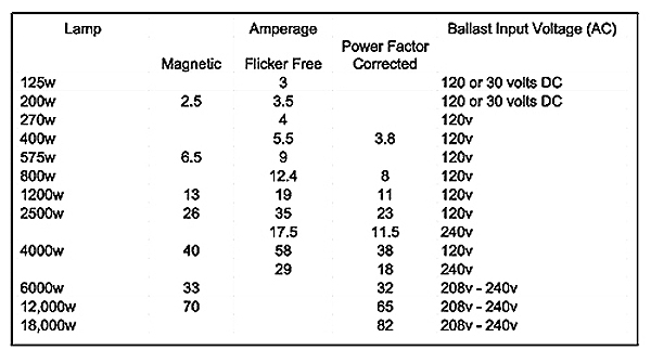
Current drawn by HMI Ballasts
We chose as our example a small indie short in order to keep the math simple. However, what is true of small lighting loads on small generators, is also true of larger lighting loads on larger generators.
For instance, before reading this article, you would have thought that you could reliably operate a 4kw HMI with non-PFC ballast on a conventional 6500W generator. But, where a non-PFC 4kw electronic
ballast will draw 58A at 120V it will overload a 6500W. To understand why, simply compare its’ Apparent Power of 6960W (58A x 120V = 6960W), to the continuous load capacity of a conventional 6500W
generator after de-rating it for a load with Leading Power Factor of .58 (6500W x .65 = 4225W.) Likewise, if you were to replace the non-PFC 4kw electronic ballast with a Power Factor Corrected one, the light would only draw 38A at 120V and have an Apparent Power of 4560W. And since, the ballast has a near Unity Power Factor, the 6500W generator would not have to be de-rated, and so could operate the 4560W Apparent Power load without a problem.
Where our tests have only compared the response of different light sources to the power waveforms of conventional AVR generators and inverter generators, let us now see how these generator types compare in the areas of speed stability, noise of operation, portability, and power capacity.
__________________________________________________________________
  

Movie Blimped
Inverter Generators
Production Features
Super Quiet
At first glance, you notice that unlike the typical “deluxe” AVR generators that use open frame designs that let everything “hang out,” the design of inverter generators consist of isolated chambers that are completely enclosed. For example, the noise of the Honda EU6500is generator has been greatly reduced by integrating a triple-chamber construction for the exhaust, engine and air intake. The exhaust chamber is now lined with a sound-absorbing material and houses a larger muffler that is secured to the frame and enclosed in the body of the generator, reducing both noise and vibration. The engine chamber is also lined with a sound-dampening material and has fully sealed panels to contain acoustic energy.
ILLUSTRATION COURTESY OF HONDA POWER PRODUCTS

Honda triple-chamber construction
The central air intake and exhaust system is designed to reduce mechanical noise by making airflow smoother by use of an air guide and intake nose. A newly designed rigid frame also aids in the sound attenuation of the EU6500i. And, instead of covering the frame with a single layer of plastic, the shell of EU6500is is made up of a layer of vibration-dampening foam sandwiched between layers of plastic. This sandwich of material prevents the enclosure from resonating which dramatically reduces sound levels.
While the totally new frame design of inverter generators in general greatly reduces noise, what makes the Honda inverter generators incredibly quiet, as well as more fuel efficient, is what Honda calls its’ micro processor controlled Eco-Throttle.
Eco-Throttle is simply the marketing name Honda uses to describe two of the characteristics of PWM inverter modules discussed above that make inverter generators considerably
quieter than conventional AVR generators. First, with their multi-pole rotors and small stator, inverter generators produce more electrical energy per engine revolution than
is produced in conventional AVR generators. Their greater efficiency, and the fact that the frequency of the power they generate is not linked to engine speed, means they can
run at much slower RPMs for a given load than a conventional AVR generator.
The second reason that inverter generators are quieter than conventional AVR generators is that their PWM inverter modules permit their engine speed to be varied with load. Which means that, at less than full load, the engine can be slowed down which tremendously reduces the noise it generates. Put simply, an inverter generator is much quieter because the engine does not have to run at full speed constantly as is the case with conventional generators. Honda calls these two features “Eco Throttle” because it results in a substantial reduction in fuel consumption. But, what is of more importance for motion picture production is that these features make inverter generators substantially quieter than traditional AVR models.
ILLUSTRATION COURTESY OF HONDA POWER PRODUCTS
 
Improved Noise Level and Fuel Consumption as a result of Eco-Throttle
Through this combination of innovative frame design and “Eco Throttle,” the Honda inverter generators achieve a noise reduction of ten decibels. Which makes them half as loud as the comparable EM7000is and ES6500 generators typically found at lighting rental houses. Honda's EU Series generators operate at 34 to 44 dBA at 50 ft. - well below what is required for trouble free location recording and quieter than our Crawford 1400 Amp “Movie Blimped” Generator.
ILLUSTRATION COURTESY OF HONDA POWER PRODUCTS

Comparative Noise Levels of Honda Generators and other sources.
Smaller Size
Inverter Generators provide stable, clean power in a smaller, lighter, quieter package. This is accomplished by integrating parts from the engine and generator set into a wholly new combination flywheel/alternator. In the case of the Honda EU6500is, this results in a generator that is more compact and 33% lighter than the comparable Honda EX5500. This is a significant reduction in footprint for a unit producing such a high power output.


ILLUSTRATION COURTESY OF HONDA POWER PRODUCTS
Combination flywheel/alternator makes Honda Inverter Generators smaller and lighter than convential AVR Generators

Solid as a Rock
As we have seen, inverter generators, like the Honda EU6500is, take a radically different approach to generating power than do conventional generators. That difference extends also to how voltage is regulated. Voltage and Frequency in conventional generators are intractably linked to their Engine/Alternator. If you recall, according to the basic principles under which generators operate voltage can be regulated either by engine speed or field strength in it’s Rotor electromagnets. Conventional portable generators use AVR systems to regulate the field strength through a DC excitation current because, in order to provide a constant AC Frequency, the motor must run at a constant speed. For this reason, portable generators with simple two-pole cores require Barber Coleman governors to govern their engines to run at a constant 3600 RPM to produce stable 60 hertz (cycle) power. Regulation of voltage through engine speed is simply not an option for this reason.
Inverter generators by comparison do not have to run at a constant speed because the AC power they output is generated from high voltage DC power that is micro-processor switched according to a PWM control logic with a voltage stability of ± 1%, and Frequency
stability of ± 0.01 HZ. This simple fact, that the voltage and frequency of inverter generators are no longer linked to their engine, offers a number of benefits for filmmakers. To understand those benefits, we need to first take a closer look at how the generator portion of inverter generators like the Honda EU6500is operate.
Since they adjust their speed to accommodate the load placed on the generator, the motors used in inverter generators have to have a wide torque range to be able to accelerate rapidly to accept an increase in load put on it. For this reason they use a high torque ‘stepper motor’ mounted on the carburetor capable of responding rapidly to signals from the inverter microprocessor control section. And, because the speed of the motor is always changing, inverter generators cannot maintain voltage output by the conventional means of regulating the excitation current in Rotor electromagnets. Instead, inverter generators use permanent magnets in place of electromagnets.
A permanent Magnet is an object made from a material that is magnetized (Neodymium in this case) and creates its own persistent magnetic field. As such, permanent magnets do not require a DC supply for the excitation circuit, nor do they have slip rings and contact brushes. And, unlike an electromagnet, a permanent magnet is not dependent on input power to the Exciter (voltage regulator) to produce and maintain the magnetic field in the Rotor. For this reason, permanent magnets offer tremendous benefits in this application.
In a conventional AVR generator, as you may recall, there is a power feedback loop from the generator output (via the Sensor Coil) back through the Exciter (Voltage Regulator) to an electromagnet in the Rotor. If the generator output is subjected to a sudden heavy load (the strike of an HMI lamp for instance), the engine bogs down, and the voltage in the feedback loop is greatly reduced, which, in turn, results in a reduction of the AVR’s capability to recover from the application of the heavy load. When a permanent magnet is used in place of this closed loop excitation circuit, the persistent magnetic field in the Rotor is independent of the generator output and consequently of sudden heavy loads. Thus the permanent magnet in an inverter generator provides stable continuous power to the inverter, enabling voltage to be regulated by engine speed rather than field excitation. The result is that the generator is much better able to sustain output current against transient loads and, therefore, it has a much lower internal reactance compared to conventional AVR machines.
Left: Conventional AVR Generator w/1200W non-pfc electronic ballast. Right: Inverter Generator w/1200W non-pfc electronic ballast
A second benefit to filmmakers in using permanent magnets in place of electromagnets in the generator’s Rotor is that inverter generators consequently have very low sub-transient impedance. If you will recall from our earlier discussion, impedance is a function of the internal reactance of the engine to changes in load. Since permanent magnet generators are less susceptible to changes in load, the power fed to the inverter module is more stable. Add the fact that the inverter completely processes the raw power (converting it to DC before converting it back to AC), the AC power it generates is completely independent of the engine. In fact, the microprocessor controller can vary the engine speed without affecting the voltage or frequency of the power the inverter module puts out. Now that the combination of a permanent magnet generator/inverter module separates the internal reactance of the engine from the power output, harmonic currents encounter very little impedance; and, as is evident in the oscilloscope shots above, there is considerably less voltage distortion at the load bus. The net benefit to filmmakers is that non-linear loads, like electronic HMI & Kino ballasts, do not adversely affect the power of inverter generators as they do the power of conventional AVR generators.

TABLE COURTESY OF KIRK KLEINSCHMIDT
A third benefit to filmmakers is that the harmonics generated by leading power factor loads, like electronic ballasts, do not affect the regulation of voltage in
inverter generators as they do in conventional AVR generators. As discussed above, the permanent magnets of inverter generators produce a persistent magnetic
field unregulated by an excitation current. Absent an excitation circuit, Armature flux generated by harmonic currents in the Stator can no longer cause erroneous
voltage regulation as is the case with conventional AVR systems. Consequently, leading power factor loads do not cause voltage regulation errors in inverter generators
as they do in conventional AVR generators. For this reason inverter generators are able to hold their voltage stable within ±1% of the mean voltage, as opposed to the
±3% of conventional generators using analogue AVRs and are much less susceptible to voltage drop and AC Frequency (Hz) as a function of load (see table above.)
The rock solid power and low sub-transient impedance of inverter generators enable you to operate larger non-linear loads on a portable gas generator than has been
possible before. For instance, we have struck 6k HMI Pars on a modified Honda EU6500is inverter generator without problem. These features of inverter generators
make them an ideal power source for motion picture production with non-linear lighting loads.

Honda's sophisticated micro-processor based "i-monitor" control system
Finally, with micro-processor based control systems, most inverter generators also incorporate a suite of temperature, voltage and current sensors to make sure everything is operating correctly and to ensure that the generators can put out extra power for short time periods to start demanding loads such as electric motors which can require three times the amount of power to start as they require to run.
New Life to Magnertic HMI ballasts
If you don’t have access to the newest Power Factor Corrected (PFC) electronic ballasts, you are better served by using the older magnetic ballasts on an inverter generator (like the Honda EU6500is) over non-PFC electronic ballasts on conventional AVR generators (like the Honda EX5500 or ES6500.) Where this is contrary to the conventional wisdom, allow me to explain some of the advantages to operating magnetic ballasts on inverter generators.
With a frequency variance of only hundredths of a cycle, magnetic ballasts will operate “flicker free” on inverter generators, without the need for costly crystal
governors, as long as you shoot at one of the many safe frame rates. Besides the extra bulk and weight of magnetic ballasts, the smaller magnetic ballasts
(575-2500W) offer the distinct advantage of being less expensive and drawing less power (13.5A versus 19A for a 1.2kw) once they have come up to speed than
the commonly available non-PFC electronic equivalents. Finally, magnetic ballasts will operate more reliably on inverter generators, than non-PFC electronic
ballasts operate on AVR generators. The reason being the leading power factor caused by the capacitive reactance of non-PFC electronic ballasts have a more
severe effect on the power waveform of conventional AVR generators than do magnetic ballasts on the power waveform of inverter generators.

Left: Grid Power w/ no load has a THD of <3%.
Center: Conventional AVR Power w/ no load has a THD aprox. 19%
Right: Inverter Power w/ no load has a THD of aprox. 2.5%.
With an inherently distorted voltage waveform (see above) of upwards of 19.5%, high impedance AVR generators (like the Honda EX5500 or ES6500) do not interact well with the harmonic currents generated by the capacitive reactance of electronic ballasts. The net result is that the harmonic currents thrown back into the power stream, result in severe voltage waveform distortion and ultimately to equipment failure or damage.
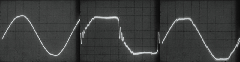
Characteristic voltage waveform of a non-PFC electronic HMI ballast on grid power (left),
on power generated by a conventional AVR generator (middle),
and power generated by an inverter generator (right)
This is clearly evident in the oscilloscope shots (reproduced above) of what results from the operation of a 1200W HMI with non-power factor corrected ballast on grid power (left), on a conventional AVR generator (Honda EX5500) (middle), and inverter generator (Honda EU6500is)(right.) The adverse effects of the harmonic noise generated by non-PFC electronic ballasts and exhibited here in the middle shot, can take the form of overheating and failing equipment, circuit breaker trips, excessive current on the neutral wire, and instability of the generator’s voltage and frequency. Harmonic noise of this magnitude can also damage HD digital cinema production equipment, create ground loops, and possibly create radio frequency (RF) interference.

Characteristic voltage waveform of a 1200W magnetic HMI ballast on grid power (left),
on power generated by a conventional AVR generator (middle),
and power generated by an inverter generator (right)
As is evident in the oscilloscope shots (reproduced above) of a 1200W magnetic HMI ballasts on grid power (left), on power generated by a conventional AVR generator (middle), and power generated by an inverter generator (right), the lagging power factor caused by the inductive reactance of magnetic ballasts has by comparison only a moderately adverse effect on the power waveform. Outside of causing a voltage spike in the inverter power, magnetic ballasts actually show a positive effect on the already distorted power waveform of the Honda EX5500 conventional generator. For this reason magnetic ballasts work better on conventional generators with frequency governors than do non-PFC electronic square wave HMI ballasts.
These oscilloscope shots show that if you don’t have access to the newest PFC electronic ballasts, the older magnetic ballasts are in fact cleaner running on portable gas generators than non-PFC electronic ballasts. And, where inverter generators like the Honda EU6500is do not require crystal governors to run at precisely 60Hz, you can operate magnetic HMI ballasts reliably on them.
Of course there are downsides to using magnetic ballasts. One down side is that you are restricted to using only the safe frame rates and shutter angles. But, when you consider that every film made up to the early 1990s were made with magnetic HMI ballasts you can see that being limited to the safe frame rates is not all that restrictive. Another downside to magnetic ballasts is that you can’t load the generator to full capacity because you must leave “head room” for their higher front end striking load.
When choosing HMIs to run off portable generators, bear in mind that magnetic ballasts draw more current during the striking phase and then they “settle down” and require less power to maintain the HMI Arc. By contrast, an electronic ballasts “ramps up.” That is, its’ current draw gradually builds until it “tops off.”
For example, even though a 2.5 magnetic ballast draws approximately 26 amps you will not be able to run it reliably on the 30A/120V twist-lock receptacle of either
a 6500W Inverter or AVR generator. As mentioned above, magnetic ballasts have a high front end striking load. So, you must leave “head room” on the generator to accommodate the strike. And, even though the twist-lock receptacle is rated for 30 Amps, 6500W generators are only capable of sustaining a peak load of 27.5 Amps on a single leg of the generator for a short period of time. Their continuous load capacity (more than 30 minutes) is 23 Amps per leg. And, if there is any line loss from a long cable run the draw of a 2.5 magnetic ballast will climb to upward of 30 Amps. To make matters worse, as we saw in the oscilloscope shots above, the lagging power factor caused by the inductive reactance of the magnetic ballast causes a spike in the supply voltage that can cause erratic tripping of the breakers on the generator or ballast. In my experience the load of a 2.5kw magnetic ballast is too near the operating threshold of an unmodified 6500W generator for it to operate reliably.

Honda EU6500i Inverter Generator with 60A Full Power Transformer/Distro
The only sure way to power a 120V 2.5kw (or even a 4kw) HMI magnetic ballast on a portable gas generator is from its' 240V circuit through a 240v-to-120v step down transformer like the one we manufacture for the Honda EU6500is (pictured above.) A transformer will step down the 240V output of the Honda EU6500is generator to a single 120V circuit that is capable of accommodating the high front end striking load, and even the voltage spikes, of either a 2.5kw or 4kw magnetic ballast at 120V (see below for additional benefits to using step-down transformers with portable gas generators.)
Since magnetic HMI ballasts will operate flicker free at all standard frame rates on them (without the need for a crystal governor), inverter generators give new production life to older 120V magnetic HMI ballasts.
__________________________________________________________________


For all their benefits true sine wave inverter generators had limited applications in motion picture production because they had limited output. It was not until the introduction of the
Honda EU6500is inverter generator in the fall of 2007 that the benefits of inverter technology became available in a generator with output comparable, if not greater, to the conventional
AVR generators commonly used in motion picture production. The benefits of inverter technology discussed above mean that inverter generators can put out 20% more power than conventional
AVR generators using the same engines. For instance, it is possible to get 7500W of continuous power in a single 120V circuit out of a Honda EU6500is generator. That is enough power
to run a lighting package consisting of a 2.5kw, 1200, & 800 HMI Pars (with PFC ballasts), a couple of Kino Flo ParaBeam 400s, a couple of ParaBeam 200s, and a Flat Head 80. Given the
light sensitivity of electronic imaging systems, this is just about all the light needed to light a large night exterior.
In order to understand how it is possible to get 7500W of continuous power in a single 120V circuit out of a Honda EU6500is generator, one must first appreciate two
things about the continuous load ratings given for generators. First, the factors generator manufacturers use to derive load ratings include not only the mechanical
components (engine & alternator), and the electrical components (circuitry & wiring), but also the prevailing electrical codes of the market for which it is intended (where & how it will be used) and the brand
image of the manufacturer (life expectancy of the product.) A quick survey of the wide range of continuous load ratings (5000W-7000W) of generators, by manufacturers other
than Honda, using the same Honda GX390 engine as the EU6500is supports this fact. Second, when Honda engineered the EU6500is it was not only for the North American market.
Like a car, Honda engineered a base model for the world market that they then customize for the different national markets. The difference between the various national models
is primarily in the power output panel, which is configured according to the electrical standards and prevailing codes of the national market in which the generator
will be used. For these reasons, the true power generating capacity of the Honda EU6500is is open to speculation.

Left: Three EU6500is and an EU3000is provide a total of 200 Amps of power for the base camp catering trucks (pictured right) of the Sandra Bullock Feature "Heat." Center:
Two EU6500s with 60A Transformer/Distros
power the refrigerators, freezers, and industrial exhaust fans of the set mobile kitchen. Right: the EU3000is powers a walk-in refrigerator trailer (located behind the van.) While, the 3rd EU6500is powers the catering truck, and the food buffet toasters and heating
lamps (right of frame) through a 60A Transformer/Distro (pictured center on a handtruck with 20A break-out boxes.)
When you compare how Honda outfits the base model of the EU6500is generator for the European and UK markets, where the standard circuit for domestic power is 230/240 Volts
and 16 Amps (3680/3840 Watts), to how Honda outfits the same generator for the North American Market, where the standard circuit is 120 Volts and 20 Amps (2400 Watts), one
realizes that the continuous power rating of 5500w for the North American Model of the generator is under-rated. Where England and Ireland have not entirely conformed to
the European Union Standard of 230 Volts, but still generate 240V power, Honda must engineer into the base model the capacity to generate 240V/16A circuits (3840 Watts/circuit) for the UK market.
Empirical tests show that, in fact, the base model is designed to generate two 240V/16A circuits or 7680 Watts (2x3840W/circuit = 7680W.)
To empirically test how much more generating capacity the base model is capable of, we tapped an EU6500is in a similar fashion to the UK model and used a step-down transformer to convert the 240 Volt output to a single 120
Volt circuit. We then used the generator's overload sensor to empirically test its' capacity with a load bank following the parameters as set forth in the manual:
"If the generator is overloaded, or if the inverter is overheated, the red overload indicator will go ON.... When an electric motor is started, the red overload indicator may come on. This is normal if the red overload
indicator goes off after about five seconds.... When the generator is operating overloaded, the red overload indicator will stay ON and, after about five seconds, current.... will shut off"
Gradually increasing the load from the load bank, we found that we could power a continuous load of up to 7680 Watts without the overload indicator coming on. When we exceeded 7680 Watts, the red indicator
blinked intermittently. When we exceeded 7800 Watts the red indicator came on continuously and power was cut off to the receptacles. Since, according to the Honda Manual it is normal for the overload indicator to come on
for short front-end loads, like electric motors starting, our results suggest that the continuous load capacity of the base model, or the EU6500is after our modification, is actually 7680 watts. And, when you consider that
electric motors require up to three times more power to start than is required to keep them running, suggests that the peak rating is actually well above 7680W. Our tests confirm that the
inverter module of the EU6500is generator is in fact capable of generating more power than is provided to us by the North American Power Output panel.

At the IATSE Local 481 Balloon Seminar we demonstrated that our modified 7500W Honda EU6500is was an
ideal power source for lighting balloons.
It makes perfect sense that Honda would engineer a continuous load capacity of 7680 watts into the base model of the generator when you consider the electrical systems of the UK countries. Where we have 15 and 20A circuits,
they have 13 and 16A circuits. Two 240V/16A circuits provides a total of 7680W (3840 Watts/circuit x 2 = 7680 Watts) which is what we found that the electronic circuit breaker in the inverter module is set for. Suspecting that
it was not just coincidental that the actual continuous load capacity of 7680 Watts is the equivalent of two standard household circuits in the UK, we took our suspicions to
Honda Motors USA, who confirmed that in fact the base model of the EU6500is generator is engineered to generate the equivalent of two UK circuits and has a continuous load capacity of 7680Watts. When confronted, they also
admitted to us that when they configure the base model for the North American market with 120V circuits, they are not fully utilizing the power generating capacity they have built into the machine for the worldwide market.

Our modified 7500W Honda EU6500is generator and 60A Full Power Transformer/Distro powering
4kw HMI and 8kw Tungsten AirStar Balloons at the IATSE Local 481 Balloon Seminar.
Even though the inverter module of the EU6500is may support continuous loads of 7680W does not necessarily mean that the generator's engine can. Quite often, when you find yourself in the situation with a conventional AVR
generator, where HMI lights that have been running fine, suddenly cut out when another light is turned on, it is because the generator engine bogs down under the additional load. As the engine rpms drop, frequency and voltage
drop as well, causing the HMI lights to cut out from low voltage. For this reason it is important to factor engine capacity whenever sizing a generator for an HMI load.
The power behind the EU6500is is Honda's workhorse GX390 engine. According to Honda literature, the GX390 is a 13HP Twin Cylinder, Overhead Cam (OHV), Liquid Cooled gas engine with a Displacement ( Bore X Stroke ) of 389cc
/ 23.7 cu. inches and a Gross Torque of 20 ft-lb at 2,500 rpm. This same engine is used worldwide by manufacturers of all kinds of power tools, from pumps to roto-tillers, and is rated with a maximum output of 9600 Watts
(13ps, 13bhp) at 3,600 RPM.

Surveying the continuous load capacity ratings of 5000W-7000W of generators by manufacturers other than Honda that use the GX390, one quickly realizes that the factors generator manufacturers use to derive these ratings
include more than just the mechanical components (engine & alternator.) To get an idea of the true power generating
capacity of this engine we need look no further than the Coleman Model PM0497000 Generator. Coleman uses the Honda GX390 engine in this conventional "industrial generator" it manufactures for the construction market. Colman
rates the Model PM0497000 Generator at 7000W continuous and 8750W peak load capacity. Where the Model PM0497000 Generator is manufactured by Coleman for the construction trades to run power equipment with high front
end loads it is probably safe to bet that Coleman is under-rating the PM0497000 generator at 7000W continuous and 8750W peak load capacity.
Using Coleman's rating of the Model PM0497000 Generator as a conservative bench mark of the engine's true capacity, and taking into account that an inverter generator draws 20% more power from each revolution of the
generator core (thanks to its multiple coils and multiple magnets generating several hundred overlapping sine waves per revolution), it is probably safe to assume that the GX390 engine in an inverter generator is
capable of generating at least 8400W of continuous and 10500W of peak power.
Where Honda does not make this information public and electronically breakers the power output at 7680W, there is no way of knowing for certain what the actual generating capacity of the GX390 engine is in an inverter generator like the EU6500is. We can however safely conclude that the GX390 provides
a quiet and efficient power plant that more than compliments the 7680W continuous power output of the EU6500is' inverter power module.
To understand why Honda under-rates the EU6500is generator in the North American market, one only has to look to the guidelines for the use of portable generators set by the Occupational Safety and Health Administration (OSHA) in this country.
In Article 29 CFR 1926.404(b)(1)(ii), OSHA exempts portable gas generators from the requirement to provide Ground Fault Circuit Interrupters (GFCIs) if they meet certain criterion. Article 29 CFR 1926.404(b)(1)(ii) reads as follows:
"Receptacles on a two-wire, single-phase portable or vehicle mounted generator rated not more than 5kW (latter increased to 5.5kw continuous load), where the circuit conductors on the generator are insulated from the generator frame and all other
grounded surfaces (a Floating Neutral configuration), need not be protected with ground-fault circuit interrupters."
What this means is that under these conditions, the manufacturer does not need to put the normally required GFCIs on a generator. It is because OSHA requires that portable generators rated for more than 5500W of continuous
load have GFCIs, that Honda, as well as other
generator manufacturers, do not rate "Home Standby" generators, like the Honda EU6500is, for more than 5500W continuous load. To understand why, we must understand how GFCIs work and why you can't have them in a generator designed for home standby
power.
OSHA requires that portable generators that do not meet the exemption above be monitored by a Class A GFCI to protect against serious harm from electrical shock. A Class A GFCI is designed to interrupt power to a circuit if it detects current
leakage that is greater than 6 mA. At 6 mA, almost all adults and children can let go of the source of a shock. At higher currents, people are progressively less able to overcome muscle contractions caused by the shock, and therefore less able
to disconnect themselves from the fault source. A GFCI will de-energize the circuit in less time than it takes to receive a harmful amount of current - which is why OSHA requires them on portable generators.

GFCI protection is a problem on a generator designed for home standby power because of the way they work. A GFCI works by monitoring the current between the hot conductor and the neutral conductor. When it senses a very small difference in current between
the two, typically three to six milliamps (0.003+/-mA - 0.006mA), it trips by opening internal current conducting contacts. The reason Home Standby generators can not have GFCIs is that, for GFCIs to operate reliably the Neutral of the generator must be
bonded to ground through the frame of the generator (a Bonded Neutral generator.)

Bonding Neutral to ground through the generator frame is a problem in home standby applications because as
illustrated in the figure below our National Electrical Code (NEC) also requires the main service head (panel) of homes to also have Neutral bonded to ground. Where that is the case, if the generator Neutral is also bonded to ground,
two parallel paths back to the generator are created, one using the neutral wire and one using the ground wire. The neutral current will then flow through both the Neutral and Ground conductors. Since the Hot and Neutral wires pass through
the ground fault sensor but the Ground wire does not, a GFCI on the generator will sense current imbalance and trip as soon as the genrator is turned on. In the case of home standby power, the Neutral in the generator cannot be bonded to ground
when the Neutral is bonded to ground in the main service panel. For this reason generators, like the Honda EU6500is, that are designed for home standby power applications have unbonded Neutrals (they are called "Floating Neutral" generators.)

While a Floating Neutral design enables it to be used for home standby power, an unmodified Honda EU6500is would not meet OSHA guidelines for use on job-sites if it were rated at its' true power because they can not
offer the GFCI protection mandated by OSHA in generators larger then 5500W. GFCIs require a bonded Neutral, the EU6500 has to have a Floating Neutral in order to provide home standby power. In other words, in the North American market Honda has to under-rate the EU6500 in order qualify for the exemption from
OSHA's mandate that they provide GFCI protection. In order to rate the generator higher, our national codes would require Honda to put GFCI protection on the EU6500is. But, if they did that, the generator would not be applicable
for home standby power which is it's primary market. This is why Honda under-rates the EU6500is at a continuous load rating of 5500W when our empiracle tests proved it is capable of much more. This is also why you do not see portable gas generators designed for home
standby power by any manufacturer (Honda, Onan, Subaru, Coleman, or Yamaha) with continuous load ratings over 5500W - they too would be required by OSHA to provide GFCI protection if they were rated for more than 5500W (use
this link for a detailed explanation of OSHA
requirements and why almost all portable generators do not meet them.) Unfortunately for filmmakers the
implication of the OSHA guidelines for portable generators is that none of the Honda inverter generators (the EU series and EM5000is) meet OSHA requirements for use on film sets. So what is a film electrician to do when they have to operate a
portable generator in wet hazardous conditions that require GFCI protection?
A 100 GFCI with our 60A Transformer/Distro meets OSHA requirements
for use of a Honda EU6500is generator on work sites.
Our system meets OSHA requirements for the use of Floating Neutral generators like the Honda EU6500is on set. Our 60A Full Power Transformer/Distro bonds the Neutral to ground on its' secondary or load side. Our
HD Plug & Play Gen-set set-up is in fact identical to that of a bonded building service head fed by a home standby generator. With Neutral and Ground bonded only in our Transformer/Distro
and not in our modified Honda EU6500is, you have a complete circuit on the load side of the Transform/Distro that creates a low resistance path (illustrated below) for fault current back to the transformer
windings and a breaker that will trip from the over-current situation.

Where this is the case, to completely comply with the OSHA requirements for the use of a EU6500is on set all you need to do is use GFCI protection downstream of our 60A Full Power Transformer/Distro. With the Neutral and Ground bonded in our
60A Transformer/Distro, in the event of a Fault, current will go to ground and GFCIs will operate reliably even when the power is being generated by a Floating Neutral generator like the EU6500is (use this link for more details.)
Our 60A Full Power Transformer/Distro offers many benefits when used with our modified Honda EU6500is (use this link for more details), but the ability to use GFCI protection in wet conditions or
locations has got to be the greatest benefit of all. Not only can you use a generator that is quiet and produces clean power, but it also makes it possible to use GFCI technology, like film style 100A GFCIs, that are specifically designed
for motion picture applications (use this link for more details about the advantages to using GFCI protection specifically designed for motion picture applications.)

100A GFCI provides ground fault protection on wet locations
There are other reasons for Honda to under-rate the Honda EU6500is, especially when their market research shows that they do not need to provide more than 5500W continuous load rating for the average consumer. One is
maintaining the Honda brand image of manufacturing generators that will last forever. Honda claims the life of the GX390 engine in their generators is an impressive 2000 hours. One of the reasons they may obtain that
kind of longevity is by under rating their generators for their consumer markets.
As we have seen Honda has several good reasons to under-rate the generating capacity of the powerful EU6500is for the North American consumer market. But, the fact that they have to keep its' continuous load rating
to no more than 5500W in order to be exempted from mandatory GFCI protection is probably the primary reasons they
under-rate the powerful EU6500is (note the higher rated Coleman generator was for the construction market and offers GFCI protection.)
__________________________________________________________________


The new Honda EU7000is generator offers all of the same production capability as did the EU6500 which it replaces. But, with improved output, noise
and fuel consumption, the new EU7000is is, without a doubt, a further evolution of the Honda inverter series of generators. In the area of fuel
efficiency, the EU7000 is the first fuel-injected model in the Honda lineup. This design feature results in a greater fuel
efficiency, extremely easy starting without the need for a choke, and longer operating times than the EU6500.

The EU7000 fuel-injector: the first fuel-injected model in the Honda lineup
The new model is also equipped with a larger 5.1 gallon fuel tank and can operate for six hours at rated load or an estimated 18 hours at ¼ load.
Fuel injection also makes the generator better able to handle large transient loads. With a gravity fed carburetor system, the EU6500 had limited
capability to respond quickly to transient loads thereby limiting its peak load capability. With fuel injected under pressure, the EU7000 can
respond more quickly, which has enabled Honda to increase the peak load rating of the generator to 7000W (the continuous load rating remains the
same as the EU6500: 5500W.)

For the EU7000, Honda Engineers have refined the triple chamber design of the EU6500
In the area of noise, the EU7000 is even quieter than the EU6500. Honda engineers improved on the already impressive sound specs of the EU6500 by refining the triple chamber design of the EU6500 (which was comprised of an exhaust [muffler] chamber, an engine chamber, and an air intake chamber) to further reduce noise and vibration; likewise, an improved centralized air intake and exhaust system helps to reduce mechanical noise. Let’s look at how this new design makes an already quiet machine quieter.

A more efficient air intake nose has been added to the intake of the EU7000’s cooling system
A more efficient air intake nose has been added to the intake of the EU7000’s cooling system, while improved air guides in the intake chamber draws air more efficiently over the inverters to improve their cooling. Likewise, improved air guides between the exhaust chamber/muffler and the engine chamber results in less airflow resistance and noise. The exhaust system of the EU7000 now features a larger capacity muffler with a muffler protector. The inside of the muffler protector is covered with sound absorbing heat resistant glass-wool and additional sound-dampening materials have been added to the EU7000’s engine chamber.

A new exhaust seal helps heat and noise to route up and out of the engine chamber to help dissipate sound
Improved seals between these three chambers contain acoustic energy more effectively and a new exhaust seal helps heat and noise to route up and out of the engine chamber to help dissipate sound. The end result of this new design is quieter operation and improved cooling performance.

Our paralleling control box for the EU7000is provides 100A output
and load sharing control to optimize the output.
Without a doubt, the biggest improvement in the EU7000 over the 6500 is that Honda has incorporated the paralleling capability that has been
available in their smaller EU series generators into this model. Paralleling EU7000s offers many benefits. By doubling up the output of two
machines, it is now possible to power larger HMIs (6-12kw), or more small lights, than has ever been possible on portable generators. Or, where
power redundancy is required in critical applications, such as live broadcast, operating two machines in parallel almost guarantees you against
a loss of power because of generator failure (if one fails, the other picks up the whole load.)

Since load sharing between paralleled generators is critical to their successful operation (see below for details), the brighter and more easily
read iMonitor digital display (above) of the EU7000 makes this important task easier. The only drawback to Honda’s paralleling system is that it combines
only the 240V output – not the 120V output (the largest 120V circuit is still 30A.) The reason for this is that, illustrated below, generators operating in parallel
share a common neutral bus, which means that any out of balance neutral current returned by 120V loads will circulate continuously between the
machines causing the heat generated by these currents to increase exponentially (see below for details.)

To avoid circulating current burning out the generator’s inverters,
Honda’s paralleling system supports only single-phase 240V loads that, by their nature, do not return current (in fact, they do not even require a
neutral conductor.) To operate 120V loads larger than 30A (4k HMIs & 5-10kw quartz lights) one must use a 240V-to-120V step-down transformer that
will convert the combined 240V output of paralleled machines to a single large (60-100A) 120V circuit with a neutral conductor. But, because there
is no physical electrical connection between the coils of the transformer’s primary and the coils of its’ secondary, a step-down transformer also
isolates the generators from the neutral current returned by 120V loads that would otherwise circulate between them and cause them to overheat
(see below for details.)

__________________________________________________________________
A Production System for a New Age
Where, the typical load placed on portable generators in motion picture lighting applications today consists predominantly of Reactive Loads like HMI & fluorescent ballasts that generate harmonics,
the conventional wisdom among Gaffers is to further de-rate the Continuous Load capacity over and above what the generator manufacturer has already de-rated the generator set for the RV or Home Standby Power
applications. The conventional wisdom is to further de-rate the continuous load capacity of portable generators because the means by which the industry has successfully dealt with harmonics has, in the
past, not been available to the user of portable gas generators.
The means by which the motion picture industry has more or less successfully dealt with harmonics - namely the over-sizing of generators, the over-sizing of neutrals, the incorporation of power factor correction circuitry in large HMI ballasts, and finally the use of generators with 2/3 pitch windings (Crawford Studio Generators) are generally not available to users of small portable generators as their primary source of power. That is because, productions using portable gas generators are using them by necessity. For budgetary or logistical reasons, it is simply not an option to upscale their generator and customize their distribution package to accommodate a heavily harmonic load. The only alternative is to de-rate the continuous load capacity of the generator and distribution equipment.
The Limit Characteristic graph for a conventional AVR generator.
Note the diminishing effect that leading Power Factor loads have on the generator's power capacity.
Where the severe harmonic noise of a typical lighting package exhibited above, can cause overheating and failing equipment, efficiency losses, circuit breaker
trips, excessive current on the neutral return, and instability of the generator's voltage and frequency (as illustrated in the Limit Characteristic graph of a conventional AVR generator above) the conventional wisdom in the past has been to not load a generator beyond 65% for more than a short period (the maximum recommend continuous load on a 6500W generator, with a continuous load rating of 5500W, would be roughly 4200 watts.) Like the generator manufacturer, by de-rating the load capacity, the Gaffer minimizes the adverse effects of high THD so that the generator will operate more reliably.
The New Math of Low Line Noise
This conventional wisdom, however, no longer holds true of inverter generators when used with Power Factor Corrected (PFC) HMI & Kino ballasts. For example, the power waveform below on the right, is the same 2500W load but with power factor correction operating on our modified Honda EU6500is Inverter Generator. As you can see, the difference between the resulting waveforms is startling. Even though the load is the same, the fact that it is power factor corrected and power is being generated by an inverter generator, results in virtually no power waveform distortion. What this means is that an inverter generator can be loaded to capacity with PFC HMI and Kino Flo ballasts without its' stator core overheating from high frequency flux change, its electrical wiring overheating from excessive resistance, and its distribution panel overheating from a high neutral return. As illustrated in the Limit Characteristic graph for an inverter generator below, the substantial reduction in line noise that results from using PFC ballasts on the nearly pure power waveform of an inverter generator creates a new math when it comes to calculating the continuous load you can put on a portable gas generator.
The Limit Characteristic graph for an Inverter generator.
Note the negligible effect that leading Power Factor loads have on the generator's power capacity.
According to this new math, it is possible to maximize the continuous load that can run off of an inverter generator, by using HMI and Kino Flo lights with Power
Factor Corrected ballasts. Where, in the past we had to de-rate portable generators because of the inherent short comings of conventional generators when dealing with the harmonic
noise generated by non-PFC electronic ballasts; now an inverter generator can be loaded to capacity. According to this new math, when you add up the incremental savings in power
to be gained by using only PFC HMI ballasts, add to it energy efficient sources like the Kino Flo Parabeam fixtures, and combine it with the pure waveform of inverter generators,
you can run more HMI lights on a portable gas generator than has been possible before. For example, the 7500W capacity of our modified Honda EU6500is Inverter Generator can power
a lighting package that consists of a PFC 2.5kw HMI Par, PFC 1200, & 800 HMI Pars, a couple of Kino Flo ParaBeam 400s, ParaBeam 200s, and Tegra 400s. Given the light
sensitivity of HD cameras, this is pretty much all the light you will need to light even night exteriors.
Left: Distorted power waveform created by Non-PFC 1200W HMI ballasts on conventional generator.
Right: Near perfect power waveform created by the same lights with PFC ballasts on inverter generator.
As we have seen, the primary factors limiting the use of HMIs on portable generators has been their
inefficient use of power and the harmonic noise they throw back into the power stream. The power waveform below left is typical of what results
from the operation of a couple of 1200W HMIs with non power factor corrected ballasts on a conventional portable generator. The adverse effects
of the harmonic noise exhibited here, can take the form of overheating and failing equipment, efficiency losses, circuit breaker trips, excessive
current on the neutral wire, and instability of the generator voltage and frequency. For these reasons it has never been possible to operate more
than a couple of 1200W HMIs on a conventional 6500W portable gas generator. Harmonic noise of this magnitude can also damage HD digital cinema
production equipment, create ground loops, and possibly create radio frequency (RF) interference.
Our 60A Full Power Transformer/Distro provides 7500 Watts of power in a single 120v circuit
from the
new Honda EU6500is Generator
The increasing use of personal computers, hard drives, and microprocessor-controlled recording equipment in production has created an unprecedented
demand for clean, reliable power on set. At the same time, the trend in set lighting is toward the use of more and more non-linear light sources that dump harmonic
noise into the power stream. Taking advantage of recent technological advances in electronic ballast design and power generation it is possible
to design a new production system that will generate clean stable set power capable of operating larger lights (HMIs up to 6kw or Quartz lights up
to 5kw), or more smaller lights, off of portable gas generators than has ever been possible before. For example, the power waveform above on the right,
is the same package of HMI lights but with power factor corrected electronic HMI and Fluorescent ballasts operating on our an
Inverter Generator. As you can see, the difference between the resulting waveforms is startling. Even though we are running the same overall load, the
fact that the ballasts are power factor corrected and the power is being generated by our an Inverter Generator, results
in virtually no power waveform distortion. For this reason, sensitive electronic production equipment will operate reliably and without damage. And, the generator is capable of operating larger, or
more smaller, lights than has ever been possible before on a portable gas generator.

In fact, something of a milestone was recently set when a commercial for the Chevy Volt was shot with nothing more than
batteries and a 60A generator. Normally, sets for car spots are cluttered with diesel generators, large feeder cables
and the multiphase distribution boxes required to power big lights, cameras, and basecamp trailers. This, however, was
the first car commercial ever made where everything was powered by batteries and a 60A Honda EU6500is generator. Use this link to see the commercial and
the behind-the-scenes “making of” video.

Set of Chevy Volt Spot powered by 60A Generator
Now that we can operate bigger, or more smaller, lights on a portable generator, the last impediment to using them in motion picture production it the noise they make.
A lot of filmmakers hesitate to use a portable gas generator on their production because of the noise. Whether you pick up generator noise on your audio tracks comes down to what generator you
use and how you use it. We have specifically designed our HD Plug-n-Play Gen-set to enable you to record clean audio even under the worse case scenario (see
sample production below.) How does it do it? We start with the super quiet Honda EU6500is Inverter generator and then augment it with a custom distribution system that enables you to operate the
generator at a distance (where it won't be heard) yet still maintain full 120V line level on set.

Our 14 Gallon Fuel Caddy enables our modified Honda EU6500is
to operate up to 20hrs without refueling
A common problem with portable generators, even the super quiet Honda Inverter generators, is that by the time you move them far enough off set that you don't hear them you have significant "Line Loss"
(often referred to as "Voltage Drop") from the long cable run back to set (if you use regular cable.) To the problem of line loss, you have the added problem that as you add load, the voltage drops on
portable generators (it is not uncommon for a generator to drop 5-10 volts under full load.) The combination of voltage drop on the generator and line loss on a long cable run can cause voltage to drop
to the point where HMI and Kino ballasts cut out unexpectantly or won't strike at all. Low voltage can also cause problems such as reduced efficiency and excessive heat in equipment, unnecessary additional
load on the generator, and a dramatic shift in the color temperature and in the output of lights (use this link for a
details .) For these reasons, portable gas generators are typically
operated too close to set where they are picked up on audio tracks. The trick to recording clean audio is to use a generator, like our modified Honda EU6500is, with a boost transformer, like our Full
Power Transformer/Distro, that enables you to operate the generator at a distance without suffering from voltage drop.
As noted above, the Honda EU6500is to begin with is much quieter than other portable generators and even Honda's older movie blimped Honda EX5500. Where conventional generators like the Honda EX5500 and ES6500
have to run full speed at a constant
3600 RPM to produce stable 60 hertz (cycle) electricity, a Honda EU6500is only needs to run as fast as required to meet the load demand. Since their engines do not have to run at full speed, and given the fact
that an inverter generator generates 20% more power per revolution of the engine, makes the Honda EU6500 substantially quieter than conventional models.
The net result is that it operates between 34 to 44 dBA at 50 ft. - half as loud (ten decibels) as the comparable EM7000is and ES6500 generators and comparable to full size movie blimped generators
like the Crawfords. But you can't park a Crawford right on set and record sound without picking up the generator either. With sound specs this good all you need to record sound with a Honda EU6500is without
picking up generator noise is a real distro system that will allow you to move the EU6500is off set (like you would a Crawford), minimize line loss over a long cable run, and provide plug-in pockets
conveniently close to set. That is where our Full Power Transformer/Distros comes in.
__________________________________________________________________

Full Power Transformer/Distros
A Transformer doubling as a distro box can be used to step down the 240V output from a generator to a single 120V circuit that is
capable of powering a big light like a 5k Quartz light or 4kw HMI Day Lite Par - thus eliminating the need for the diesel generator typically required to power
these lights. And, where with the right lights (pfc electronic HMI ballasts) you can utilize the full capacity of a generator, a transformer/distro will enable you
to power more smaller lights off of the generator than you can without it because it provides you access to the full continuous rated power capacity of the generator in a single
circuit (60A in the case of our modified Honda EU6500is and 84A in the case of the Honda EB10000.)
Honda EB10000 with Voltage Select 84A Transformer/Distro
and 14 Gallon Fuel Caddy
Single Large 120V Circuit
How do they do it? A transformer typically consists of two sets of coils or windings (a basic two-winding transformer is shown in the Figure below.) Each set of windings is simply an inductor. AC voltage is applied to
one of the windings, called the primary winding. The other winding, called the secondary winding, is positioned in close proximity to the primary winding, but is electrically isolated from it.

The alternating current that flows through the primary winding establishes a magnetic flux, some of which links to the secondary winding and induces a voltage across it.
The magnitude of this voltage is proportional to the ratio of the number of turns on the primary winding to the number of turns on the secondary winding. This is known as
the “turns ratio.” A 240V-to-120V step-down transformer has a turns ratio of 2 to 1. To maximize flux linkage with the secondary circuit, an iron core is used to provide a low-reluctance path for the magnetic flux.
Generator Wiring Schematic
Used to step down the 240V output of a generator, a transformer will give you the full capacity of the generator in a single 120V circuit. To understand why this is, we have
only to look at the wiring schematic of a conventional AVR generator above.
As you can see from the wiring schematic, if you measure the voltage from each hot pin of the generator’s 240V 4-pin receptacle to ground it will be 120 volts, and if you measure
the voltage between the two hot pins of the 4-pin receptacle you will notice that it is 240 volts. As illustrated below, the 120 volts of the two poles adds up to 240V because the 120V circuits
are on opposing legs of a single phase circuit and 180 degrees out of phase with each other.

The voltage of opposing legs of a single phase circuit add while the current carried on the legs subtract.
Now if you feed the 240 Volt output of the generator to the primary side of a transformer, on the secondary or load side of the transformer it will be converted to 120 Volts in a single circuit that is the sum of the
two single phase legs (as illustrated below.) And, as you can see by the wiring diagram above, since the 240V output comes directly from the generator windings, by-passing the breakered branch circuits of the
generator power output panel, the transformer gives you the full capacity of the generator in a single large 120V circuit.

As we saw above, things get quite a bit more complicated with inverter generators. Unlike the simple two-pole alternator of the AVR generator in the wiring schematic above, an inverter generator uses a core that consists of
multiple Stator coils and
multiple Rotor magnets. Each full rotation of the engine produces more than 300 three phase AC sine waves at frequencies up to 20 kHz, which is considerably more electrical
energy per engine revolution than produced in conventional two pole AVR generators. A fixed diode bridge rectifier then converts the more than 300 three phase AC sine waves
to a DC voltage (about 200 V). Single phase AC output is then generated from the high voltage DC by a inverter module with voltage and frequency set by micro-processor
controlled switches using a PWM control logic.
ILLUSTRATION COURTESY OF KIRK KLEINSCHMIDT
The three phases of the inverter generator process: high frequency AC converted to DC; DC inverted to stable clean 120V, 60 Hz AC.
Because of the addition of the inverter unit, there is not a direct circuit to the alternator windings as there is in the AVR
generator depicted above (not that we could use the high frequency 3-phase power anyway), but the principle is the same. A transformer will step-down the 240V output of an Inverter, just as well as that of a two pole alternator,
the wiring
just gets a little more complicated on the generator side. If the generator is one of our modified Honda EU6500is, a 240V-to-120V step-down transformer will convert the
enhanced 7500W/240V output to a 60A/120V circuit. If the generator is 10kW Honda EB10000, a 240V-to-120V step-down transformer will convert the
enhanced 10000W/240V output to a 84A/120V circuit. Either way, now that the full power of the generator is available in a single 120V circuit, it is capable of powering larger lights, or more smaller
lights, than has ever been possible before on a portable generator.

60A Full Power Transformer/Distro on location
Now that you have access to the full power of the generator in one circuit, you can load the generator more fully. Without a transformer you can never fully utilize the available power of a portable generator because the load of
a light has to go on one circuit/leg of the generator or the other. For example, when plugging lights into the power outlet panel of a Honda EU6500is Inverter Generator, you reach a point where you can't power an additional 1kw
light because there is not 8.4 amps available on either one of the factory installed 20A outlets/leg of the generator. With a Transformer/Distro you can still add that 1kw light because the Transformer/Distro not only accesses
power through a higher rated circuit (the 30A/240V Twistlock), but it also splits the load evenly over the two legs (4.2A/leg) of the generator on that circuit.
A Honda EU6500is & our 60A Full Power Transformer/Distro powering
PFC 2.5 & 1.2 HMI Pars, PFC 800w
Joker HMI,
Kino Flo Flat Head 80, 2 ParaBeam 400s, and a ParaBeam 200
And, because the Transformer/Distro perfectly balances the load of what ever you plug into it, the
generator is capable of handling the larger load more easily because it is perfectly balanced.
Simplifies Electrical Distribution
The best part about using a Transformer/Distro is that it splits the load of what
ever you plug into it automatically. The iMonitor display on the Honda generators makes it especially easy to load them
to the max. Simply plug in lights. When the load wattage displayed on the iMonitor reaches 7500 Watts (EU6500is) or 10'000 Watts (EB10000) you are fully utilizing the power capacity of the generator.

An overload alarm on the iMonitor display will
tell you if you inadvertently overload the Transformer/Distro. You no longer have to carefully balance the load over the generator's two 20A/120 circuits/legs as you
plug in lights because the Transfomer/Distro does it for you automatically. Now that you are able to fully utilize the generator's
available power, you are able to power larger lights, or more smaller lights, than you could without a Transformer.

Night exterior scene lit with HD P&P Pkg.
For example, our modified Honda EU6500is Inverter Generator with our 60A Full Power Transformer/Distro is capable of powering a 2.5kw Par along with 1200, 800, &
400 Pars with PFC ballasts, plus a couple of Parabeam 400s and Parabeam 200s. Given the light
sensitivity of HD Camcorders, this can constitute a complete location lighting package for a low budget HD
Digital Cinema production.
Cushions the Impact of Large HMI & Tungsten Heads
Another advantage to our system is that our Full Power Transformer/Distros cushion the sudden impact of switching on large Tungsten lights (like 5ks) or striking large
HMIs. This feature is particularly beneficial with older 2.5-4KW HMIs with 120V magnetic ballasts becuase they draw more current during the initial striking phase of the electrical arc and then
“settle down” and require less power to maintain the arc (by contrast, an electronic ballasts “ramps up” its’ current draw gradually during the striking phase until
it “tops off.”) The problem operating older 2.5-4KW 120V magnetic HMI ballasts on portable generators is that because the high front end load of the strike occurs on only one leg of the generator, it
creates a sudden impact for which the AVR (Automatic Voltage Regulator) cannot adjust in a timely fashion and the output voltage dips. Before the AVR control can compensate, the light shuts off before
it is fully up to color temperature. Not only does your light not stay on, but shutting off before it comes fully up to color temperature, the metals in the bulb fuse inside the globe -
damaging the bulb.
Because our Transformer/Distro automatically splits the load of whatever you plug into it evenly over the two legs of the 240V circuit of the generator, it greatly reduces the impact
on the generator of sudden large loads. Split into two smaller perfectly balanced loads by our Transformer/Distro, the high front end striking load of older 120V magnetic ballasts, or
the sudden load of switching on a large tungsten light like a 5k, has a less severe impact on the generators Automatic Voltage Regulator. In combination with the voltage boost
we design into our Full Power Transformer distro (see below for details), this feature of transformers assures that output voltage will not dip too low under large loads.

Night exterior Two Shot lit with HD P&P Pkg.
Compatible with Standard Film Distribution Equipment
Configured with the industry standard GPC (Bates) receptacles, our Transformer/Distros not only enable you to get more useable power
out of the generator, but they also greatly facilitate the distribution of power on your set. The 60A (EU6500is) and 100A (EB10000)
GPC (Bates) receptacles, on our Transformer/Distros will enable you to power a 5kw Quartz, 2.5kw HMI Par, or even a Power Factor Corrected 4kw HMI Par.
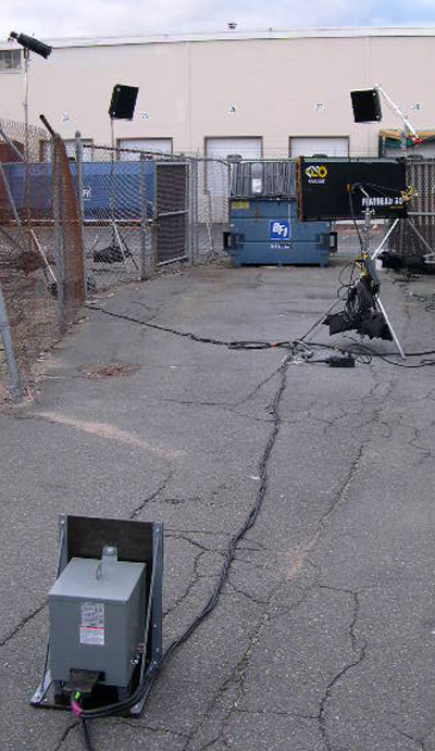
Distro System consisting of 60A Full Power Transformer/Distro, 2-60A GPC (Bates) Splitters, 2-60A Woodhead Box.
Even though the generator is 100' away to reduce noise, plug-in points remain conveniently close to set.
With the addition of GPC (Bates) extension cables, Splitters, and fused GPC-to-Edison Breakout boxes, our Transformer/Distros enable you to run power
around your set - breaking out to 20A Edison outlets at convenient points. The best part is that no matter where in the distribution system you plug in, the
Transformer/Distro automatically balances the additional load, so that you don't have to. If you are using our modified Honda EU6500is generator, you simply plug in lights
until the load wattage displayed on the iMonitor of the generator control panel reaches 7500Watts. An overload alarm on the iMonitor display will tell you if
you inadvertently overload the 60A Transformer/Distro (same for the EB10000 generator with our 84A Full Power Transformer/Distro.)

60A GPC (Bates) Splitters and Woodhead Box
60A Woodhead Box running Power to Light PFC 800W ballast (left) and PFC 1200W ballast (right.)
Line-Loss Compensation
A common problem with portable generators, even the super quiet Honda Inverter generators, is that by the time you move them far enough off set that you don’t hear them you have significant “Line Loss”
(often referred to as “Voltage Drop”) from the long cable run (if you use regular cable) back to set. Low voltage on set can cause problems such as reduced efficiency and excessive heat in equipment,
unnecessary additional load on the generator, and a dramatic shift in the color temperature and in the output of lights.

For example, the effect of line loss on tungsten lights can be dramatic because their output falls off geometrically as the voltage decreases. For example a 1k lamp operating at 90% rated voltage (108V) produces about 68% of its normal light output - your 1kw lamp is now a 650W lamp. But, that is not all, as the light intensity decreases, so does the Kelvin color temperature of the emitted light. In the case of
fluorescents, HMIs, and LEDs, because their power supplies are typically of a “constant power” type, they will draw more current as the line voltage decreases in order to maintain constant power to the lamp. In the case of
generator output, voltage loss translates into an exponential loss in power. That is because, if you double the ampere load on the cable, the voltage drop also doubles, but the power loss increases fourfold. What this means is
that when a distribution system has a large voltage drop, the performance of the generator (its maximum effective load) is reduced. For these reasons it is worthwhile understanding the dynamics of line loss and how to mitigate it.
Line Loss
Line Loss is the erosion of voltage over a long distance caused by the resistance of electrical cables. The severity of line loss increases with the amount of current carried by a particular conductor,
so you can anticipate a significant line loss any time there is a fairly long run of cable and the cable is loaded near its' maximum ampacity rating. The three major variables that affect the amount of
line loss are length, wire thickness, and amperage load. Here is why:
1) The resistance of a conductor increases directly with its length. The longer the run, the greater the line loss.
2) The resistance of a conductor decreases in proportion to its cross-sectional area. The larger the conductor the less line loss.
3) Voltage drop varies with the load. The larger the amperage load, the larger the line loss.
How much is too much line loss? Or, put another way, what is an "Allowable Voltage Drop?” According to the National Electrical Code (NEC), the amount of voltage drop that still allows acceptable
performance from equipment operating on it, and does not cause harm to the equipment, is the definition of “Allowable Voltage Drop.” As to what that figure is, lets look to the specific section of the NEC that covers line loss.
The NEC does not regulate allowable voltage drop specifically, but in a fine print note (FPN) in Section 215.2(A)(3), the code reads:
FPN No.2: Conductors for feeder as defined in Article 100, sized to prevent a voltage drop exceeding 3 percent at the farthest outlet of power, heating and lighting loads, or combinations of such loads, and where the maximum total voltage drop on both feeders and branch circuits to the farthest outlet does not exceed 5 percent, will provide reasonable efficiency of operation.
In Lay Men’s terms, what this note says is that if a voltage drop in a distribution system does not exceed 5%, the voltage will provide “reasonable efficiency of operation.” At 120V line level, this translates to a voltage drop of no more than 6 Volts, or the voltage should not drop below 114V from line loss. How likely is it that we will encounter unacceptable line loss operating lights on a portable gas generator? Very!
Let’s take as a practical example the use of a non-Power Factor Corrected Arri 1200 Electronic Ballast on a portable generator to light the deep background of a night scene. So that we do not
pick up generator noise on our audio tracks, we will likely have to move the generator, even the super quiet Honda Inverter generators, around the corner of a building or operate it out of our grip
truck. In order to do so will require running, let’s say 200’ of cable from the generator to where the camera is on set. However, it is likely that we will have to run another 100’ of cable from
the camera position to the light if it is lighting the deep background of our shot. What kind of line loss can we then expect over a 300’ cable run and will it be acceptable?
To calculate voltage drop (Vd) you would use the following equation:

According to this equation we need to know the following factors in order to calculate the voltage drop (Vd) our non-PFC 1200W electronic ballast will cause over a 300’ cable run:
Cm: The cross-sectional area of a wire measured in circular mils (cmil). For the sake of this discussion let’s assume we are running regular Hardware Store style 14/3 extension cables which have a cross-sectional area of 4107 cmils.
L: The length of the wire in feet. This is the one-way distance from the source to load. Note that in the equation, this number is multiplied by 2 to get the two-way distance the current has
to flow to complete the circuit. In our example we would then enter 300’.
I: The current carried by the cable. According to the manufacturer’s website, the non-PFC Arri 1200W electronic ballast
has an Apparent Power of 2290VA which means that it will draw roughly 19 amps at 120V (2290VA /120V = 19.08A.)
K: The specific resistance of the material making up the conductor. Since we are using copper cable, K would be 10.8 at 25 degrees C.
As you can see, the math is getting pretty complicated. Since there are Line Loss Calculators for this kind of thing available online (at
www.stealth316.com/2-wire-resistance.htm), let’s use one of those instead. If we enter the parameters for our example into the calculator (at the bottom) we get the results in the table below, or a line loss of nearly 15 Volts (14.781) when powering a non-PFC 1200W electronic ballast on 300’ of 14 Awg cable. Where the allowable voltage drop according to the NEC is 6V at 120V line level, our drop is more than double the allowable amount. If we look at the effect of this voltage drop on the ballast, we see why it is not allowable by the NEC.

Since the non-PFC Arri 1200 Electronic Ballast we are using is a “Constant Power” electronic ballast it will draw more current to compensate for the drop in voltage to maintain the ballast’s Apparent Power of 2290VA. At 105V it will then draw 21.81A amps (2290VA/105V = 21.81A.) Since the Arri Ballast has an operating range from 90-125V, it is not likely that the ballast will shut off from under voltage, but it is very likely that the 20A breaker providing over current protection to the generator’s Edison U-Ground receptacles will trip and shut the light off.
What can we do? We can move the generator 100’ closer to set. Even though we now pick it up faintly in our audio tracks, we have reduced our cable run to 200’ overall. If we now enter 200’ for our
cable run in the calculator we get the results in the table below, or a line loss of nearly 10 Volts (9.7869) when powering a non-PFC 1200W electronic ballast on 200’ of 14 Awg cable.

Operating at 110V, the non-PFC 1200W electronic ballast will now draw roughly 20.82 Amps (2290VA /110V = 20.82A) to compensate for the drop in voltage in order to maintain the ballast’s Apparent Power of
2290VA. While the breaker may not now trip, you can be certain that the cable and plug ends which are rated for only 15 Amps will start to heat up at nearly 21 Amps of load. While still not in the range of what the NEC considers an allowable voltage drop, it may be tolerable.
Are we in the clear? Not quite. The resistance of copper is not the only cause of line loss. Heat that occurs when a connection is weak or loose, when cable is frayed, when a connector is only partially
inserted, or when a connector or conductor is loaded beyond its capacity also can cause line loss. Whenever you push a circuit to its' maximum capacity, its' weak links will be exposed in the form of heat.
Heat increases resistance, and therefore line loss, and heat also further degrades the cable insulation which causes further line loss.
In this case, it has been my experience that, more often than not, the plug-ends of the multiple stingers running power to the ballast over-heat because they are carrying in excess of 20 Amps when they are only rated for
15 Amps. The increased resistance that results from the heat causes the line voltage to the ballast to drop further and so it has to draw more current to maintain its’ 2290VA Apparent Power. If say the voltage drops an additional 5 Volts (to 105V) because of loose or overheated connectors, a non-PFC 1200W electronic ballast will again draw 21.81A Amps and the 20A breaker providing over current protection to the generator’s Edison U-Ground receptacles will trip and shut the light off.
Skin Effect
The area of the cross sectional diameter of a conductor used by DC current (left), Low Frequency AC Current (center), High Frequency AC Currents (right).
Let’s say, for the sake of argument, that we are operating our 1200W HMI on a Honda EU3000is which doesn’t provide over current protection to its’ Edison U-Ground receptacles. Are we in the clear? Still
not yet. As you may recall from our discussion above, one of the adverse effects that the Harmonics generated by non-PFC electronic ballasts can have on a distribution system, is “skin effect.” As we saw above, harmonic
frequencies are always higher than the 60Hz fundamental frequency. Where THD is high, the higher frequencies create a phenomenon, known as “skin effect”, where the higher frequency causes the electrons to flow toward the
outer sides of a conductor. Since the flow of the electrons is no longer evenly distributed across the cross sectional diameter of the conductor, more electrons are flowing through less copper and the resistance of the
conductor increases.
The increase in resistance reduces the ability of the conductor to carry current (it's as if we were using a smaller wire), resulting in greater voltage drop over shorter distances
and overheating of the conductor.
And, as we saw above, the increase in resistance from skin effect due to harmonics is apprecialby more significant in the jacketed multi-conductor cables (10/2 or 12/3) commonly used with small portable generators,
than with the larger gauge feeder cables (single conductor #2, 2/O, & 4/O) used to distribute power from tow plants, making significant line loss a very real possibility when operating harmonic generating loads like non-PFC electronic HMI ballasts on portable generators.
Even if voltage drop as a result of skin effect, is slight, there is one final factor working against us. To the problem of cable line loss, over heating plug ends, and skin effect, you also have the
added problem that as you add load on portable generators their voltage output drops. As the table below suggests, it is not uncommon for a generator to drop 5-10 volts under full load.
TABLE COURTESY OF KIRK KLEINSCHMIDT
The 1200W ballast that last drew 21.81 Amps at 105 Volts will now draw 23.79 Amps at 95 Volts from the combined effect of skin effect and load on the generator. If our light continues to operate, what is the practical affect of this line loss? One adverse affect is that we have diminished the capacithy of our
generator. The overall voltage drop of 25V causes our ballast to draw 4 more Amps than it would otherwise. That is a considerable loss in the capacity of our generator when you consider that a Kino Flo
Parabeam 400 only draws 2 Amps. If we are able to eliminate the voltage drop in our example we would be able to operate two more Kino Parabeam 400s on our generator - that would be an appreciable increase in
production capability.
Diminished generator capacity is not the only adverse affect to voltage drop. Since there is no 20A fuse to provide over current protection on the Honda EU3000is, we now have a potentially hazardous situation. Since it has an operating range from 90-125V, the ballast may still not shut off from under voltage. Now drawing nearly 24 Amps through a receptacle rated for only 15 Amps and on extension cords only rated for 15 Amps, the excessive load of the light will likely melt the receptacle or a plug end; or worse, start a fire.
How did we find ourselves in this hazardous situation? To summarize, by the time you move a portable generator far enough off set that you don’t hear it you have significant voltage drop from the long
cable run back to set that can cause problems - especially with lights like non-Power Factor Corrected (PFC) 1200W HMIs that operate at the threshold of a 20A circuit to begin with. If from line loss
from a long cable run, increased resistance from an overheated plug-end or skin effect, or voltage drop because of a large load on the generator, the draw of the
1200W ballast will climb well over 20 Amps. Anyone with first hand experience operating “Flicker Free” 1200W HMIs on portable generators will not find the results of these calculations surprising, since
they have probably suffered their consequences without knowing why. Since, we routinely need to load cables to near their maximum ampacity and run them out a couple hundred feet, how can we avoid these problems.
Some portable AVR generators permit you to mitigate line loss by increasing the voltage at the power source (inverter generators do not.) While a 5% adjustment of the generator’s output is usually
possible by increasing the field strength of the alternator, I do not recommend this approach to mitigating the adverse effects of line loss. Increasing the
voltage at the source has two potential hazards. Equipment being powered at the upstream end of the cable run (such as a battery charger plugged directly into the generator’s power output panel will be
over voltage (the battery charger is toast.) Second, because voltage drop is proportional to amperage load, if the amperage load is reduced suddenly, any remaining equipment will be over voltage. For
example, if a big light is suddenly turned off, the voltage jumps up and the remaining load is over voltage (the sound cart is toast.) Increasing the voltage at the source (the generator) does nothing
to solve the problem of voltage drop: it merely leaves you with a workable voltage after the voltage drop occurs. The generator is still having to work a great deal harder to power the load because the
exponential power loss still occurs. This results in a loss of efficiency, greater fuel consumption (in the case of the generator), and a reduction of the maximum power available from the generator.
The only way to truly reduce these effects is to reduce resistance by adding copper (step up to a larger cable), and/or use a boost transformer to boost voltage at the end of the cable run. In our HD
Plug & Play Gen-set we do both.

2010 BET Hip Hop Awards “Director of the Year” Nahala Johnson, aka "Mr. Boomtown", directing his latest Rap Video: an outdoor dance party with DJ and dancers on top of a speaker stack (upper left.)
So that you can record sync sound without picking up the noise of even a Honda EB10000 (72db @ 23ft.), our HD Plug & Play Gen-set is designed so that you can run 200-300 ft (or more) of cable between the generator and our Full Power
Transformer/Distro and still have full line level (120V) on set. How does our system eliminate the drop in voltage from line-loss that you get using standard electrical cords? By using a larger gauge
cable to carry a smaller load, our system greatly reduces the voltage drop from line loss. And to compensate for what inevitable voltage drop will still occur from a long cable run, as well as the
voltage drop on the generator from a heavy load, we also build into our Full Power Transformer/Distros a voltage boost capacity. By assuring that you will have full line level (120V) on set, our
system permits the generator to be further away, where you won’t pick it up in your audio tracks, while your plug-in points remain conveniently close to set. It eliminates time consuming multiple
cable runs to the generator and the hazards of voltage drop to distribution equipment, lights, and other production equipment no matter where it is plugged in.

Our modified Honda EU6500is supplies power to set (far left.) Our 60A Full Power Transformer/Distro compensates for line-loss of 300’ cable run (left center) to assure 120V line level to 4K HMI (far right), Speaker Stack Amplifiers, Set Monitors, Battery Chargers, & DIT station (Center.) 60A Bates Splitters, Extensions, and Gang boxes distribute power from Transformer around set (right center.)
To demonstrate how our system works, let’s take the same example of a non-PFC 1200W HMI operating on a portable generator 300’ away. So that we do not pick up generator noise on our audio tracks, we run
200’ of heavy gauge 250V 10/3 Twist-lock feeder cable from the generator to our Full Power Transformer/Distro on set. From the Transformer/Distro, we run another 100’ of 120V 6/3 Bates extension cable from the camera position to the light. What kind of line loss can we now expect over our 300’ cable run and will it be acceptable?
Let’s calculate the line loss on the first leg of our cable run first. Since, the Transformer/Distro automatically splits the load of what ever is plugged into it evenly over the single phase circuit
of its primary side, we are now running 9.5 amps on each cable conductor instead of the 19A we ran before. And, we are running our smaller load on a larger conductor (10 Awg cable instead the 14 Awg cable
before.) If we enter these new parameters for our example into the line loss calculator we get the results in the table below, or a line loss of only 1.93 Volts when powering a 1200W HMI on 200’ of 10 Awg
cable. And, the 30A/250V Twist-Lock plugs of our heavier feeder cable won’t overheat under the smaller 9.5 A load. Unlike the 15 Amp U-Ground Edison plugs we used before, our 30A/250V Twist-Lock plugs won't cause a hot spot, won’t add resistance, and won’t cause additional voltage drop that will cause the
ballast to draw more power and trip the breaker.

Where this is the line loss on just one of the two 10 Awg conductors of the 240V circuit, is this our effective voltage drop? Yes and no. No, in the sense that it is only the line loss on each conductor
of a single phase circuit feeding the primary side of our step down transformer. The voltage drop we experience in a practical sense is what
we get on the secondary side of the transformer where we would plug in our light. To calculate that, we simply divide the 236.14V being fed to the transformer after losing 1.93V to line loss on each of
its two conductors (240V - [2 x 1.93V] = 236.14V) by 2 (the 2:1 step-down ratio of the transformer.) What we get is a voltage output of 118.07V on the transformer secondary, or an effective voltage drop
of 1.93V. So, yes, 1.93V is our effective line loss thus far.
What accounts for the appreciably less line loss? If we go back to the three major variables that affect the amount of line loss covered at the outset - cable length, wire thickness, and amperage
load - we see that the line loss is appreciably less in this case because 1) the resistance of a conductor decreases in proportion to its cross-sectional area (we are now using a larger conductor), and 2)
voltage drop varies with the load. The smaller the amperage load, the smaller the line loss (we have cut the load on each conductor in half by using a transformer to step-down from 240V to 120V.)

To the 1.93 Volt drop from our 200’ 10/3 Twist-Lock feeder cable run, we need to add the line loss we will have on the 100’ run of 120V 6/3 Bates extension cable. If we enter these new parameters
for our example into the line loss calculator we get the results in the table above, or a line loss of only .76 Volts when powering a 1200W HMI on 100’ of 6 Awg cable. The total line loss under our
system then comes to only 2.7 Volts (2.69V), which is well within the 5% acceptable voltage drop mandated by the NEC, and 589% less than what we experienced running 300 ft of Hardware Store style
14/3 extension cords.
To compensate for this inevitable slight line loss, and the voltage drop we can expect on the generator from running it near full load, our Full Power Transformer/Distros offer a voltage boost capacity to assure full line level (120V) on set.
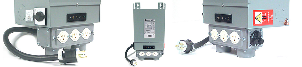
Left: "Select" Upgrade, Center: 60A Full Power Transformer/Distro fully tricked-out w/ "Select" Upgrade & Edison Break-out Box, Right: Edison Break-out Box
Our standard Transformer/Distro is designed to boost the voltage on the load side (secondary) of the transformer by 5 percent. For instance, if you were to plug the Transformer/Distro directly into a genertor running with no load
and feed the supply side (primary) of the transformer with the generator's 240V output, you will get 126 Volts out on the secondary side where you would plug in lights. We have designed this slight boost
into our standard Transformer/Distro to
compensate for the slight line loss that is unavoidable over a long cable run, and the voltage drop on the generator under load.
For instance, if we fed our standard Transformer/Distro the 236.14 volts we would have 200' away from a generator operating the 1200W non-PFC HMI in our example above (240V from the generator – 3.86V
line loss to cable – 5V drop on generator from the load), 121.47 volts would come out on the secondary side where you plug in (115.57V Output of a straight 2:1 step-down ratio + 5.90V boost
of 5% boost to primary voltage after step-down.) This example shows how the slight boost we build into our standard Transformer/Distros, not only enables you to place noisier generators, like the 10kW Honda EB10000, further
from set where they won't be heard, but also assures that the supply voltage on the secondary side of the transformer does not drop too low. By comparison, without the line-loss compensation of our
Transformer/Distros, to avoid the severe voltage drop in our example above you would have to move the generator closer to set where it will definitely be heard on the audio tracks.
"Select" Models allow you to adjust for line-loss to maintain 120V on set
The "Select" upgrade for our Transformer/Distros (optional in 60A, standard in the 84A), enable you to adjust the amount of voltage boost in two 5% steps. This enables
you to maintain full line level (120Vs) regardless if the supply voltage has dropped to 228V, or even 216V, from line loss and load running on the generator. To find the optimum switch setting, our
"Select" upgrade also includes a built-in volt meter that tells you if the line level is too low or too high.

A good example of how our Transformer/Distro makes it possible to record clean audio tracks even under the worst of conditions is the indie short "Toothbrush." In this story of mistaken identity produced by
Guymanly Productions, a pivotal scene takes place in the middle of a near vacant parking lot of an all night convenience store. With no building or other sound barrier within a reasonable distance to block the
sound of the generator, Gaffer Aaron MacLaughlin had no recourse but to put it behind their grip truck as far from set as possible. As you can see from the photos below, he ran 300' of twist-lock extension cable
from the generator to our Transformer/Distro hidden behind a newspaper box.

Left: Scene in parking lot. Center: Transformer/Distro hidden behind newspaper box (set 200' in distance.) Right: Generator baffled by truck (Transformer/Distro
300' in distance.)
From the Transformer/Distro he then ran 200' of 6/3 Bates Extension to set where he broke out to 20A Edison receptacles using a 60A
snack box. While running the generator near full capacity with a lighting package that consisted of three 1200W HMI Pars and two 1k Baby Quartz Fresnels, he experienced no appreciable voltage drop on set even
after a 500' cable run because our Select Transformer/Distro was able to compensate for both the line loss of the cable and voltage drop of the generator under near full load.

This example shows how the variable boost of our Select Transformer/Distros, not only enables you to place the generator further from set where you won't hear it, but also assures that the supply voltage
on the secondary side of the transformer does not drop too low. By comparison, had Aaron run 500' of standard 14 Awg electrical cord he would have experienced a line loss alone of 24.5V (according to the line loss
table above.) With that severe a voltage drop, his HMI ballasts would probably have cut out from low voltage as he added additional loads on the generator. Without the line-loss compensation
of our Transformer/Distros, he would have had to move the generator closer to set where it would be picked up on the audio tracks.
Now that our distro system won’t cause unnecessary voltage drop, eliminating line loss all together just becomes a matter of good set practices. Always bear in mind that Resistance, heat, and line loss
also occur when a connection is weak or loose, when cable is frayed, when a connector is only partially inserted, or when a connector or conductor is loaded beyond its capacity. Also, bear in mind that
circular coils of current carrying cable create impedance, resulting in line loss and increased heating. Good set practices, such as checking for good contact between connectors, locking connectors
tightly, taping connectors where necessary, avoiding circular coils, and replacing overheating parts, will finally rid you of the annoyance of inexplicable line loss and failing equipment.
It is well worth following these good set practices because maintaining full line level will assure that lights will draw their minimum load, distribution equipment will not overheat, and generators will deliver their full power.
It also assures that lights, like the new Arri 1800W Baby Max, that operate at the threshold of a 20A circuiit will operate reliably (more details below.)
Enables the Reliable Operation of the Arri 1800W Baby Max on Portable Generators

1800w Baby Max
Another benefit to our Full Power Transformer/Distros is that they enable you to reliably operate the new 1800W Arri Baby Max on portable generators. The problem with operating the 1800W Baby Max
on generators is that, like non-Power Factor Corrected 1200W ballasts, it also operates too close to the threshold of a 20A circuit to operate reliably. Even with Power Factor Correction circuitry built into it, the ballast of the
new 1800W Baby Max has an Apparent Power of 2450VA which means that it will draw 20.5 amps at 120V. And because, like the non-PFC 1200W ballast in our example above, the new 1800W PF ballast is also a Constant Power ballast, it will
draw even more current to maintain its' Apparant Power if voltage drops. To determine how much more current it will draw, we can look at the electrical specifications on the manufacturer's nameplate as we did the non-PFC 1200W electronic ballast above.
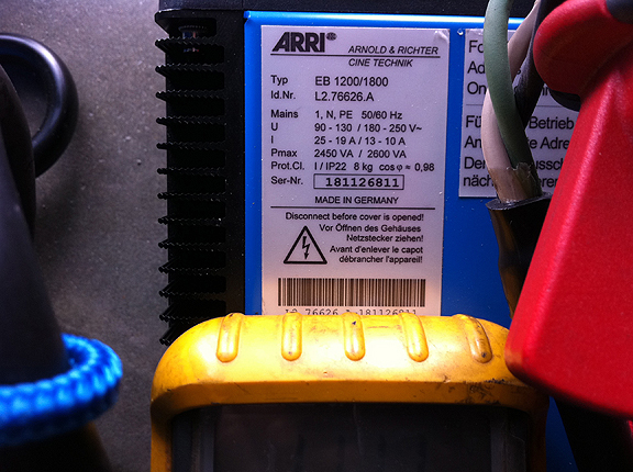
The Electrical Specifications for the Arri EB1200/1800 Ballasts
The first thing you will notice is that the ballast has a range of Apparent Powers - 2450VA to 2600VA. The reason for this is that, given how close the ballast operates to the threshold of a 20A/120V circuit, Arri has designed the ballast to draw
less power than it would otherwise under lower voltages by turning off its' CCL (Compensation of Cable Losses) feature so that it does not trip 20A breakers. The electrical specifications on Arri's new 1800W PFC ballast (pictured above) indicate it will draw 19A of current ("I") at 130 Volts ("U") which translates to
20.5 amps at 120V - right on the threshold of a 20A circuit. As we saw above, if there is any line loss from a long cable run, increased resistance from an overheated plug-end, or voltage drop because of a large load on the generator, the draw of the Arri
1800W ballast will climb well over 20 Amps and trip a breaker.

A Honda EX5500 AVR Generator powering two Arri M18 Heads with 150’ Stinger run.
To illustrate this drawback of the Arri EB1200/1800 ballast, I ran 150’ of stingers from a Honda EX5500 to power two Arri M18 heads. Then using a stinger pigtail with the outer jacket removed, I put a True RMS Amp probe on the “Hot” conductor. As you can see from the photos attached here, the voltage at the ballast dropped from 115V to 102.9V (from a combination of Line Loss on the cable and load on the generator) and the current climbed to 21.51A.
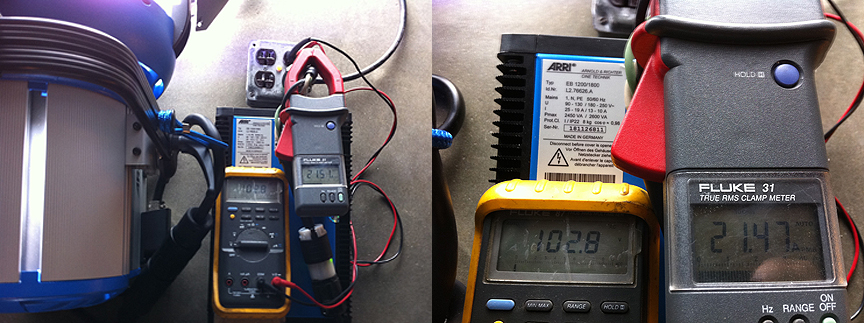
After a 12V drop from Line Loss and VD from generator load, an Arri M18 drew 21.51A at 102.9V
Arri is guilty of a bit of hyperbole when they claim the Baby Max is “the brightest light that you can plug into the wall.” Lately, they have been footnoting that claim as
follows: ““Into the wall” denotes a single, 20A 120VAC electrical outlet on a single circuit.” They make that disclaimer because the Arri 1800W Baby Max was designed to
operate on a real film distribution system where you bring the 20A receptacle to the light, rather than an extension cord to the receptacle. When you can run a 60A Bates extension
and drop a Snack Box next to the ballast you won’t have a problem with voltage drop. But, if your style of shooting requires that you run multiple stingers to plug into the
generator outlet, you will likely have problems with the plug-ends or the generator receptacle overheating and causing the breaker to overheat and trip.
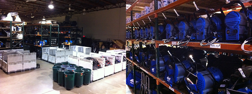
Our warehouse and some of our 20 M18 systems
The more reliable way to power a 1800W Baby Max on a portable gas generator is from it’s 240V circuit through a 240v-to-120v step down transformer, like one of our
Full Power Transformer/Distros. As discussed previously, either of our Transformer/Distros will convert the 240V output of a generator into a single large 120V circuit that is more than capable of
powering the 18.75A load of a 1800W Baby Max. In addition, the heavy-gauge feeder cable we use between the generator and transformer, eliminates the appreciable voltage drop you would have using
standard electrical cords. While, the slight voltage boost we have designed into our Transformer/Distros assures that the supply voltage on set will not drop below 120V and cause the 1800W ballast to
draw more than 18.75 Amps. Finally, our Ful Power Transformer/Distros use standard film distribution equipment so that you can use GPC (Bates) Extensions and Snack Boxes to run power to the light
(breaking out to 20A Edison pockets next to the ballast), rather than having to run multiple stingers from the ballast back to the generator.
By eliminating the line loss from long cable runs, increased resistance from overheated plug ends, and voltage drop from large loads on the generator, our Full Power Transformer/Distros
assure that the Arri 1800W Baby Max will operate reliably on portable generators. When you consider that the Arri 1800W Baby Max has the output of a
2.5kw Par, but the light quality of a Fresnel, being able to operate it reliably on a generator is a big benefit to using our Full Power Transformer/Distros (use this link for
more details on the photometrics of the Arri 1800W Baby Max.)
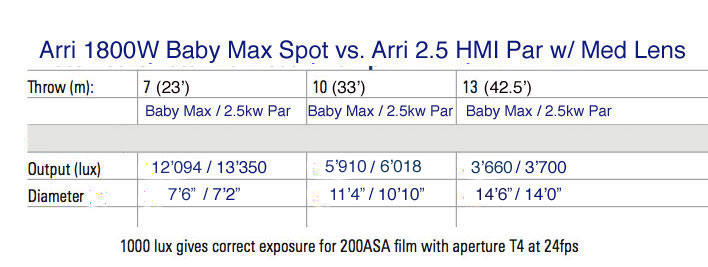
Our Transformer/Distro also enables you to run 1800W Arri Baby Maxs on “house power” from common 240v household outlets as well. Just like it does with a generator, a transformer will step down the 240V power of common high voltage household outlets to a single 120V circuit capable of powering multiple 1800W Baby Maxs. By giving you access to more “house power” through common 240V household outlets, a transformer also enables you to run a real distro system without the need for a dangerous tie-in or expensive tow generator. The ability to run multiple 1800W Baby Maxs off of common 240V house receptacles, or the 240V receptacle of portable generators, is one of the best reasons that I can think of to use transformers on set.
Electrical Hazard Protection
Portable generators are quite often used to provide power in situations where it is not possible to get a large tow plant. Since, many of these situations also include working in, on, and around water (to provide power on boats,
beaches, and around remote lakes and streams) we have designed our HD Plug & Play Pkg. Gen-set to meet OSHA requirements (most portable generators do not) and operate safely in wet environments.
Left: Ready for rain on the set of "Gasp." Center: Two 4kw Pars operate on a 10kw Honda EB10000 Generator through our 84A Full Power Transformer/Distro.
Right: 100A Shock Block GFCI downstream of Full Power Transformer/Distro offers Ground Fault Protection for entire 100A distro system.
The danger of water is that it greatly reduces the resistance between you and the ground. In wet grass, moist soil, standing water, or a swimming pool, the minerals in water make it a conductor.
In fact, water is a better conductor when it is mixed with the minerals of soil. A muddy field is more conductive than a freshwater pool. Salt water (which is essentially what the human body is
made of) is a better conductor than fresh water. Neither is a very good conductor, but both can still pose a threat to life if a Ground Fault exists. To get a shock a person must become part of
a closed circuit. When working in rain (real or manufactured) everything and everyone tends to get wet, and wet hands, gloves, and feet pose little resistance should you come into contact with a Fault.
To protect people from electrical hazard in wet locations certain precautions must be taken. Light fixtures must be properly grounded and GFCI protection should be used on all circuits.
The requirement to ground portable generators, and the effectiveness of GFCIs used in connection with them, have been debated in the industry.
Some technicians believe that, like larger studio units, portable gas generators do not require grounding and that GFCIs will function regardless of the grounding arrangement. What fuels the debate
is a general ignorance that there are two distinct types of portable generators – those with Floating Neutrals and those with Bonded Neutrals. Which type of generator you are using determines whether
it should be earth grounded with a ground electrode and what grounding arrangement is required to make GFCIs operational.
To understand what it means to properly ground requires a basic understanding of the principles of electricity and electrical distribution, and of the parlance of the electrical trade. For example, the word “ground” is used in four totally different ways by electricians.
1) Equipment Grounding: The U-shaped prong on an Edison plug is for the equipment grounding wire. Grounding wires are not meant to carry current under normal circumstances. They carry current only when there is a Fault inside a piece of equipment causing the metal housing to become electrified.
2) Grounded Neutral: The Neutral wire is sometimes called a “Grounded Neutral.” The reason for this will become clear in a moment. Grounded Neutral wires are not to be confused with grounding wires.
3) System Grounding: The Neutral buss of an electrical service is grounded to the earth by use of a grounding electrode (ground rod) sunk into the earth. The grounding electrode conductor is the wire that makes this connection.
4) Ground Fault: The unintentional grounding that occurs when a live conductor accidentally comes into contact with a metal surface. This type of Ground Fault is usually arcing and can be extremely destructive. When a Ground fault occurs in a grounded system the safety device (fuse or circuit breaker) will activate which opens the circuit and current will not continue to flow
Since the nature of electricity is not easy to grasp, analogies can be helpful in understanding the basic concepts in their simplest form.
Current, Voltage, Resistance
To understand the characteristics of electricity - Current, Voltage, Resistance - it helps to compare it to water. Like water, electricity flows. This flow is called current, measured in Amperes. Like water pumped up a hill, it will
always flow back to its’ source. That is, electricity always travels in a circuit or a loop. When the circuit is broken, so is the flow of electricity. Like water pressure, electricity requires power to push it through a circuit.
The power needed to push the flow of electricity through the circuit is Voltage. Electricity encounters friction in the form of electrical Resistance, measured in Ohms. Like plumbing, the bigger the diameter of the electrical pipe
(wire), the smaller the Resistance. The smaller the diameter of the electrical pipe (wire), the higher the Resistance. The higher the Resistance, the bigger the pressure or Voltage needed to push the same current the same distance.
Like water, when electrical current is given alternate paths to travel, most, but not all, of the current will follow the path of least Resistance.
The plumbing of electrical circuits, are conductors. Electricity flows through the conductor with the least Resistance. Most metals have low Resistance to electricity and make excellent conductors.
Circuits
Electrical current travels from a power source (such as a generator), passes through a load (such as a light), and returns to the power source to complete a circuit. If there is not a complete circuit - a switch is open or an "Air Gap" exists from a missing link or connection - current does not flow anywhere in the circuit. The part of the circuit going out from the power source to the load is called the Hot or “positive” side.

The part of the circuit returning from the load to the power source is called the Neutral or “negative” side. Ideally, the current going out from the power source (Hot) should be equal to the current returning (Neutral.) For obvious reasons, it is preferable that current travels only through electrical wire or other suitable conductors, not people.
Grounding
In a grounded electrical system, the Neutral is intentionally connected to Ground, making the Ground an alternate part of the electrical circuit. The grounded circuit can therefore be completed by electricity going either from the
source to the load (through the positive side) and back to the power source (through the negative side) or from the source through the positive side to Ground (negative side) and back to the power source. The “Ground” can be either
an equipment grounding conductor that connects all the non-current carrying metal parts of the system, or in its’ absence, the earth.
Faults
An electrical fault can be compared to a leak in a water pipe. A fault occurs when current partially leaks out of the intended path or circuit, using another path to return to the power source. As a result the current flow at
the hot side is not the same as the current flow at the neutral side. Almost all electrical equipment leaks some current, this includes stingers, lights, feeder cables, and ballasts. Even dust that has collected inside a light
housing can be a conductor and cause a current leak. If the leak is large enough it can cause a fault. Common causes of faults are frayed or nicked electrical cords, deteriorated insulation in lights and ballasts, or moisture.
There are two types of Faults:
1) Current leaking directly from hot to neutral – When the current leak is severe enough that there is no effective resistance, it produces a short circuit. In such a case, circuit breakers or fuses in the circuit will trip or blow, de-energizing the circuit.
2) Current leaking to ground – This is called a Ground Fault. In a grounded system the current leak completes the circuit by going back to the generator’s winding through the ground (either an equipment grounding conductor or the earth.)
Faults can be deadly. In the absence of an effective equipment grounding conductor, electrocution can occur when a worker holds a faulty piece of equipment that is energized by a current leak and the current returns
to its’ source using the individual to complete the circuit.

A prime example is an aluminum ladder contacting an overhead power line – the fault returns the current to its source using the ladder, the worker, and the ground as its’ conductor to complete the circuit.
In a true ungrounded or “Floating Ground” system, the circuit is isolated from the earth. For this reason, if a Fault occurs and there is another path back to its source (the equipment ground), the current has no tendency to
go to earth ground to complete the circuit, unless the system becomes grounded by having more than one fault in the circuit (a double fault situation.)
Grounding falls into two categories: Systems Grounding and Equipment Grounding.
Systems Grounding – is accomplished by attaching one current carrying conductor of an electrical system to Ground at the source of power, this is called the Neutral or common leg. The Ground
can be the earth or in the case of portable generators, the frame of the generator as long as it is isolated from earth.
Equipment Grounding – is accomplished by attaching all of the non-current carrying metal parts of a system together and connecting them to the same systems ground as the Neutral at the
source of power (a Bonded Neutral system). The equipment ground is a safety loop that works in conjunction with the over-current protection to protect people against shock from a faulty piece of
equipment that has developed a short (contact with housing.) If no grounding wire were connected anyone who touched the fixture, would (as illustrated above) offer current an alternate path for
it to complete the circuit by traveling through their body and the ground, back to its’ souce. The individual making contact with energized housing would receive a shock.
With a grounding wire connected to the housing, electricity seeks the path of least resistance, and the bulk of electricity completes the path back to it's source (completing the circuit) through the grounding wire instead. If the neutral wire of the circuit is also bonded to the generator
frame (a Bonded Neutral system), when a Fault occurs, it creates an over-current situation, which trips the breaker and removes the Fault from the circuit.

One way to think of equipment grounding is that it is the intentional connecting of all metal parts of a system together through a ground wire so that all exposed conducting surfaces have the same
potential. That way if someone touches any two metal surfaces they will not receive a shock because they will not experience any difference in potential.
The other intentionally connected conductor of an electrical system is the Neutral which is sometimes referred to as the "common conductor". The Neutral is a circuit conductor, not an equipment
ground, and if it is grounded to keep it at the some potential as earth, or ground, it should be grounded at the source and nowhere else.
Portable Generator Types:
There are two types of portable gas generators. In one, the Neutral system (the common conductor) is not bonded to the frame of the generator or to the earth ground lead. Rubber mounts are used to
isolate the generator winding from the frame and the equipment grounding conductors. As a result, there is no specific Hot leg and
Neutral leg wiring arrangement for the generator winding connection to the receptacle. As a consequence, both legs on the receptacle
are potentially Hot legs. For this reason generators that do
not bond the Neutral circuit to the frame are commonly called “Floating Neutral” generators. The Floating Neutral configuration is common for applications such as connection to a recreational
vehicle and connection to home power where the transfer switch does not switch out the Neutral to Ground connection. When used as a stand-alone power source (a “Separately Derived System” in
NEC parlance), OSHA requires the frame of Floating Neutral generators to be bonded to earth ground for reasons we will explore shortly. This involves putting a rod 8’ into the earth
and attaching a ground cable from the rod to the generator frame.

The other type of portable generator is more akin to a Crawford Studio Generator in that it has the Neutral bonded to the frame of the generator (as illustrated above) and so is called a "Bonded Neutral" generator.
Since Bonded Neutral generators offer a high degree of protection against ground faults (if there was a fault to the frame, the generator’s circuit breaker would trip eliminating the fault)
whether they require an earth ground is up to the AHJ (Authority Having Jurisdiction.) The AHJ, depending on where the work is taking place, may be the local city electrical inspector, the
fire marshal, or the studio’s safety officer. The AHJ is the ultimate authority for what practices will be allowed on set.
Bonded Neutral Generators:
It might seem odd to bond the equipment grounding wires to the Neutral, because the Neutral carries current. It might seem like this would make the entire equipment grounding system live. It does quite the opposite.
Let’s look at why this is.
When a source of electrical power is completely isolated from earth ground (not to be confused with equipment ground in this case), the only fixed quantity is the voltage potential created between the wires coming out of the alternator of the generator. The voltage potential from any
part of the circuit to ground is not defined. With no reference to ground, it is as if the phases are floating. To use an analogy: it is like a ship floating on a gentle sea – even though the
ship rises and falls with the swells of the ocean, the relationship of the keel (a phase leg) to the deck (the Neutral) doesn’t change. In such an arrangement, we know the phase potential is 120V higher, but we don’t
really know higher than what? Like the ship, the relation to the ground is floating (called a Floating Ground arrangement), changing slightly as the waves gently ungulate up and down. And, just like a ship navigating the open sea, this arrangement (an
isolated power source) can function just fine, as long as nothing comes along to make a connection to earth ground.
“Generators mounted on trucks or trailers shall be completely insulated from earth by means of rubber tires, rubber mats around metal stairways and rubber mats under any type of lift gate or jacking device. Metal supports for trailers shall be insulated by means of wooden blocks. Safety tow chains shall be secured so as to not touch the ground. If complete insulation is not possible, a grounding electrode system shall be installed per the National Electrical Code, Article 250.52.”
In fact, it is the preferred set up for power that is distributed from a generator according to the guidelines (see excert from safety bulletin #23 above) established by the Safety Committee of the
Contract Service Administration Trust Fund (CSATF), an industry wide administrative body (governed by the collective bargaining agreement by and between the Producers, The International Alliance of
Theatrical Stage Employees ("I.A.T.S.E."), the Moving Picture Technicians Artists and Allied Crafts of the United States, its Territories, and Canada ("M.P.T.A.A.C."); as well as the collective
bargaining agreements by and between the Producers and the Basic Crafts Locals (Article 18)).

But as specified in the OSHA Guidelines for Grounding of Portable Generators (above), isolating the generator from ground is only permissible when the equipment grounding system, consisitng
of the non-current carrying metal parts of
equipment and the equipment grounding conductor terminals of the receptacles, is bonded to the generator frame and the Neutral conductor is also bonded to the frame as illustrated above (use this link for the
complete guidelines). If the generator is
mounted on a vehicle, the frame of the generator must also be bonded to the frame of the vehicle.
When this is the case, the figure below, illustrates how a Floating Ground arrangement offers protection against ground faults.

1) A fault in a metal fixture energizes the entire housing as soon as the circuit is turned on.
2) Since, electricity seeks the path of least resistance back to its’ source, the bulk of the
fault current will travel through the equipment grounding wire, instead of the individual making contact
with the housing, because it is of a much lower resistance than the individual. The individual offers
the current a higher resistance path because it can not complete a circuit through them since the system
is insulated from the earth.
3) Because the ground wire and the neutral wire are bonded at the generator bus with a grounding
jumper, the current carried by the ground wire back to the generator bus creates a dead short
(over-current situation). The fuse or circuit breaker pops in response.
Even with their Ground floating, Bonded Neutral generators offer a high degree of protection. With the generator winding connected to the equipment grounding conductor, a low resistance path is established to carry fault
current back to the generator winding to create an over-current situation and trip the breaker. Since, electricity seeks the path of least resistance back to its’ source, the bulk of the fault current will travel through
the grounding wire, instead of the individual making contact with the housing.
While a Floating Ground configuration of a Bonded Neutral generator offers a high degree of protection against Ground Faults in equipment, it is less than ideal. For instance, if someone were to touch a grounded part of the equipment
housing while making good
contact to ground (while holding a metal railing), then they could receive a slight shock equal to the difference in potential between the arbitrary floating power source and ground.
For this reason, the AHJ (Authority Having Jurisdiction) may none-the-less require the system be grounded by attaching the Neutral bus of the generator to earth ground via a grounding
electrode (ground rod.) Connecting a
grounding electrode to the Neutral bus of a power source gives the source a relation to ground – it establishes zero-potential between Neutral and Ground. The phase and Neutral wires are
not just 120V from one another, the phase is now 120V above ground. It is like draining the ocean, with the boat resting on the bottom, the relationship between the keel and deck are fixed
relative to the ground. With the difference in potential between the arbitrary floating power source and Ground eliminated there is no potential difference between the lamp housing and hand
railing to cause a shock. No appreciable current needs to flow through the grounding electrode conductor to establish this relationship, but once it is established, all equipment connected
to the power source has the same zero-potential relation to Ground - the system is grounded.
Whether a generator may be run as an isolated system without grounding electrode, or may be required to be grounded via a grounding electrode, depends ultimately on the AHJ (Authority Having
Jurisdiction).
Floating Neutral Generators:
There is no question that a generator system with a Floating Neutral requires grounding with a grounding electrode. As we saw above, OSHA guidelines for the grounding of portable
generators does not allow for isolating the generator from ground when the Neutral conductor is not bonded to the frame along with the equipment
grounding conductors. The reason being, that when the Neutral is not bonded to the
equipment grounding system, over-current breakers offer no protection in the event of a double fault and GFCIs will not operate reliably if they are not placed properly in the distribution system.
To understand why this is the case, it helps to understand first why technicians are not endangered by electrocution from current going to ground if there is only one fault in the system.
In a Floating Neutral system, technicians are not endangered by electrocution from current going to Ground
as long as there is only one fault in the system. Since the Ground wire and the Neutral wire are not bonded at the generator bus, the equipmet grounding wire does not offer a path for the
fault current to complete the circuit back to the generator windings. In effect an open circuit, current will not travel it and so the fault current does not even go to Ground. The figure below, illustrates why that is the case.

1) A fault in a metal fixture energizes the entire housing as soon as the circuit is turned on.
2) Since the ground wire and the neutral wire are not bonded at the generator bus, and
the generator is not grounded to earth by an grounding electrode, the equipmet grounding wire
does not offer a path for the fault current to complete the circuit back to the generator windings.
Therefore, the fault current does not go to the equipment ground wire
3) If the generator frame is completely insulated from the ground (a Floating Ground),
an individual making contact with the energized housing does not present an alternate path
for fault current back to the generator windings. An open circuit, the fault current does not go
through the individual and ground back to its source.
But, in the event of a double Fault - one on the Hot, and a second in the Neutral - a path (circuit) is created for Fault
Current to return to the generator windings through an individual making contact with the energized housing because the individual now grounds the system. Since the equipmet ground wire is not
bonded to the generator windings, it does not offer in the event of a double Fault an alternate path of lower resistance. Where the individual/ground route is now the path of least resistance,
the Fault Current travels through the individual and the ground back to the generator windings through the second Neutral Fault - delivering a shock to the individual. If either
of the Faults is high resistance, the current will not be high enough to open the breaker, and the individual will receive a sustained shock that can be potentially fatal. The
Figure below illustrates why an individual receives a shock when there are two Faults.

1) Current goes out on the hot (black conductor) to the light housing fault.
2) Even though current travels on the ground wire (if it is in good condition), current also
travels through the worker's body into the earth back to the generator windings, because there
is no clear return path because of the un-bonded condition.
3) Current enters the generator frame and goes back to the generator winding through the second Fault
on the Neutral side. If either of the faults is high resistance, the current will not be high enough to
open the breaker. However, the currrent will be high enough if the equipment grounding conductor is faulty (the grounding
pin is broken or there is a bad connection) to give the individual touching the housing a shock.
4) The generator’s circuit breaker may trip in response, but only if enough current flows through the
second fault to create an over-current situation.
5) The worker, however, is exposed to electrical shock until the breaker operates because no GFCI is present.
The inherent risk in using Floating Neutral generators lies in the fact that the neutral of the generator winding is neither grounded to the generator frame nor
to the grounding pin of the receptacle. This deficiency makes operation of the protective device (breaker or fuse) unreliable because in a two Fault situation, fault current has no definite
path as it does in a Bonded Neutral generator. For example, a fault current that, under these circumstances, is too low to trip a breaker or blow a fuse will also travel through an
individual making contact with the energized housing and deliver a potentially life threatening shock.

To isolate a portable generator from earth requires insulation between all metal points and the ground.
Since all equipment leaks some current, it is not uncommon to have two or more Faults in a system. A defect in the generator, a poorly insulated or defective extension cord, defective insulation
in a lamp housing, or defective plug, can all produce Faults (to name just a few causes.) While these Faults may have sufficient resistence to not leak much current in dry conditions, wet conditions
can change the situation dramatically. When working in rain (real or manufactured) everything and everyone tends to get wet. Water is a conductor. Salt water
(which is essentially what the human body is made of) is a better conductor. Neither is a very good conductor, but both will greatly reduce the resistance of a Ground Fault (where one exists),
so that it now becomes a threat to life. To get a shock a person must become part of a closed circuit. Rubber boots are good insulators when you come into cantact with a Fault in dry conditions,
but pose little resistance to making you a part of an electrical circuit should you come into one in wet conditions. And, since it is difficult to completely insulate a portable generator from ground (wet ground, rain, or even
high humidity can cause a generator to be inadvertantly grounded) the risks of shock greatly increases in wet conditions (see the study by The Construction Safety Association of Ontario (CSAO) below). Floating Neutral
generators are deceptive because they give the appearance of a safely grounded system when, in fact, they are not. Their receptacles accept a plug with a grounding pin, but in
the receptacle the grounding pin is connected only to the generator frame and not to the generator winding (neutral). The user is given a false sense of security.
How dangerous are shocks?
Most people think that high voltage causes fatal shocks, this is not necessarily so. The amount of current flowing through the body determines the effect of a shock. A mili-ampere (1 mA) is 1/1000th of an amp; a current of 1 mA through the body is just barely perceptible. Up to 8 mA causes mild to strong surprise. Current from 8 to 15 mA are unpleasant, but usually the victim is able to free himself or to “let-go” of the object that is causing the shock. Currents over 15 mA are likely to lead to “muscular freeze” which prevents the victim from letting go and often leads to death. Currents over 75 mA are almost always fatal; much depends on the individual involved; how much muscle mass, body condition and condition of the heart.

If the fault is high Resistance (making only loose contact with the housing), the leak current may not be high enough to open an over-current breaker. And, if the grounding conductor is faulty (the grounding pin broken or bad
connection), the Shock Current may be high enough to cause cardiac arrest.
To protect against serious harm from electrical shock, the circuit must be monitored by a Class A GFCI (Ground Fault Circuit Interrupter). This type of device will interrupt the circuit if it detects current leakage that is greater than 6 mA. At 6 mA, almost all adults and children can let go of the source of the shock. At higher currents, people are progressively less able to overcome muscle contractions caused by the shock, and therefore less able to disconnect themselves from the fault source. A GFCI will de-energize the circuit in less time than it takes to receive a harmful amount of current.
A GFCI works by monitoring the current between the Hot conductor and the Neutral conductor. When it senses a very small difference in current between the two, typically five to six milliamps (0.005 - 0.006mA), it trips by opening
internal current conducting contacts. It will typically perform this function in the event of either a Hot-to-Ground Fault where current takes a path to Ground other than through the Neutral or in the event of a Grounded Neutral
Fault caused by the Neutral and the equipment grounding conductors being electrically connected by a low Resistance path between them somewhere downstream of the GFCI device. When a Grounded Neutral Fault condition exists, the GFCI
device will trip the instant current is introduced on the circuit.

Normally, the difference in current between the Hot and Neutral conductors is zero. The component in a GFCI device that monitors current and senses an imbalance or difference between the current
flowing out on the Hot conductor and the current flowing back to source on the Neutral conductor is referred to as a Differential Current Transformer (CT). In the event that some of the current returning to Ground is passing
through you instead of the Neutral conductor, the CT will sense the imbalance and open the internal contacts to stop the flow of current through the GFCI device and through you.

A GFCI will not prevent a person who is part of a Ground Fault Circuit from receiving a shock, but it will open the circuit so quickly that the shock will be below levels which will inhibit
breathing or heart action, or the ability to “let-go” of the circuit. A GFCI will not protect against short circuits or overloads. The circuit breaker or circuit protector in the control panel, which supplies power to the circuit, provides that protection. A GFCI is not a substitute for grounding or over-current protection – it should be considered a supplemental part of the circuit.
To ground or not to ground is a complicated issue. On the one hand, if you have a Bonded Neutral system, and you can effectively isolate it from earth ground, there is good reason not to ground it.
It is a common misconception that circuit breakers and ground rods are there to protect you. A circuit breaker is there to prevent fire created by heat from an over-current or short-circuit
and protect the equipment. The amount of current it takes to electrocute a person is much smaller than the amount needed to trip a circuit breaker. Add the fact that a ground rod will never
pass enough Fault Current to trip an over current device and you realize that they are not there for personal safety. Where this is so contrary to popular belief, allow me to explain.

As the Figure of a Utility Line-men above clearly demonstrates, even though there will be current traveling on the grounding electrode, because of the high impedance of the
rod, not enough will travel on it to open a breaker. Using Ohm's law, if we calculate how much Fault Current a ground rod will pass to the source through the earth at 25 Ohms
(the prescribed impedance of Ground according to the NEC) at 120 volts, we find that a ground rod will only allow for 4.8 amps to flow through it. 4.8 amps will not open any breaker save a GFCI.
An electrical shock current of one hundred milliamps (100mA or 0.1A) is a very serious shock capable of causing paralysis of the lungs and heart muscle. The smallest circuit breaker we use is 20A –
that’s about two hundred times more current than is needed to kill you. So in the final analysis, a ground round will not pass enough Fault Current to trip an over current device, that is the job of
the equipment grounding circuit conductor. As Article 250.4 (5) of the NEC explains, bonding is to provide a path for Fault Current:
“Article 250.4 (5) Effective Ground-Fault Current Path. Electrical equipment and wiring and other electrically conductive material likely to become energized shall be installed in a manner that creates a permanent, low-impedance circuit capable of safely carrying the maximum ground-fault current likely to be imposed on it from any point on the wiring system where a ground fault may occur to the electrical supply source. The earth shall not be used as the sole equipment grounding conductor or effective ground-fault current path.”
In short, ground rods and circuit breakers provide almost no increase in safety for people. They do not provide equal potential nor do they clear Faults. Installing a rod for a generator with
Bonded Neutral will only provide a path for a person to get in between the source and return. In fact, a case can be made that the installation of a ground rod decreases safety. Short of two Ground
Faults (one in the Hot conductor and one in the Neutral), there is no potential to the earth without the rod. But, as soon as you bond the system to the earth there is potential to earth when the ground is bonded to the Neutral.

Simply using a GFCI on an ungrounded Floating Neutral generator will not ensure a safe system, and can in fact be misleading. A GFCI will not operate reliably if one side of the winding is not
grounded to the generator frame because Fault
Current has no path back to the winding to complete the circuit. Only when Neutral is bonded to Ground, will current go to Ground to complete the circuit when there is a current leak. In other
words, a complete circuit is required to create an imbalance and cause the GFCI to trip. GFCI test circuits can also be misleading when they are used on Floating Neutral
generators. On a Floating Neutral generator, the test button will draw power from the Hot through the CT and back through the CT again to the Neutral via a Current Limiting Resister.
The discrepancy caused by the Current Limiting Resister in the test circuit (illustrated above)
will initiate the GFCI to trip even though there is in fact no Ground Fault Circuit for Fault Current to go to if there were a Fault. The false positive received by GFCI test circuits on ungrounded
Floating Neutral generators does nothing to eliminate faulty equipment.

These issues related to ground fault protection with Floating Neutral generators like the Honda EU series are well documented by The Construction Safety Association of Ontario (CSAO) in a
report on a series of tests they conducted that uncovered significant problems in using GFCIs on portable generators. While the CSAO conducted their tests to determine the effectiveness of
GFCIs used on portable generators in typical construction scenarios, their findings are equally applicable to motion picture and event staging production applications. The GFCIs used in the CSAO tests were of both the extension cord and receptacle type (pictured above.) A rheostat was used to simulate the current leak to Ground (Ground Fault).
Generators connected to GFCIs were tested on wet ground, dry surfaces, and an isolated surface (the back of a pickup truck). In addition, tests covered variable grounding conditions: proper earth ground, earth ground with some
resistance, no earth ground.
Based upon their tests, the CSAO report drew the following conclusions (the complete report is available on-line at http://www.ihsa.ca/images/pfiles/24_RR004.pdf):
1) In the case of ungrounded Floating Neutral generators, where the Neutral is not bonded or grounded but "Floating", GFCIs failed to trip even when the current leak
reached higher than acceptable levels. Without a Neutral bond, electricity did not leak to ground to trip the GFCI - creating a possibly hazardous situation in the event
of a second Fault if the GFCI is not located properly in the distribution system.
2) GFCI test buttons functioned regardless of the GFCI's operability. The buttons cannot be used to test the effectiveness of GFCIs or grounding. The test button should only be
used to test GFCIs after grounding has been established.
3) Grounding can vary from one place to another, even when both are relatively close. In one test the GFCI tripped when the generator was grounded in wet earth but failed to trip when the
generator was grounded 1OO feet away in soil that was drier and better drained.
4) Testing also proved that wet surfaces can ground generators (both Floating Neutral and Bonded Neutral types) in Floating Ground arrangements - creating a possibly hazardous situation
in the event of a Ground Fault. GFCI protection is required for this reason.
5) Proper placement of GFCI protection is different for Floating Neutral and Bonded Neutral generators.
The results of the CSAO’s test, support what we determined earlier. First, ungrounded Floating Neutral generators did not present a ground path for Fault Current to travel to create an imbalance sufficient enough
to trip a GFCI when a Ground Fault existed. Second, simply grounding one side of the winding of a generator (establishing a Bonded Neutral) without also adding
GFCI protection is inadequate. Although a Bonded Neutral increases the probability that the circuit breaker would trip on a Ground Fault, current
levels could still not be high enough for a breaker to protect personnel from a shock. A combination of grounding the generator winding and adding a GFCI is
necessary. Finally, GFCIs only operated reliably when the generator was earth grounded. A ground rod establishes an alternate Ground Fault Circuit for electricity to travel back to its source via earth.
Splitting the Fault Current, a ground rod ensures the imbalance required to trip a GFCI (see Electrical Hazard Protection for the Entertainment Industry for details.)
Before we explore the implications of OSHA’s Guidelines for the use of portable generators in motion picture production, I would first like to highlight one other problem inherent in Floating
Neutral Generators. As illustrated in the Figure below, the accidental reversing of Ground Conductor and Neutral Conductor in an extension cord or lamp cord can lead to a potentially hazardous
condition when used on a generator with a Floating Neutral and no GFCI protection.

1. Current goes out on the hot conductor (black) to light. Note: The grounding conductor
is not connected to the winding of the generator (no connection between the neutral and ground)
and a GFCI is not used.
2. Current returns on the neutral (white) (shown in red) to the cord connector.
3. Current transfers to the grounding conductor from the receptacle and goes to the generator
frame and into the earth.
4. Current goes through the earth, through the victim, to the light housing, to the light ground wire.
5. Current goes through to the cord connector and transfers to the neutral, and from the receptacle
back to the generator winding.
6. Worker is connected across the generator winding and so receives a potentially fatal shock.
The implications of OSHA’s Guidelines for the use of portable generators in motion picture production:
For the reason illustrated here and above, OSHA requires that all portable generators on work sites have their Neutral bonded to the equipment grounding system and be equipped with GFCI protection.
So that they can provide an industrial generator that will pass OSHA job site inspections, manufacturers like Honda provide special industrial generator lines that meet these requirements. The EB
generators are Honda’s “Industrial Generators.” The EB3800, EB5000, EB6500, and now the EB10000 are Neutral bonded and GFCI protected to meet OSHA jobsite regulations.
The 10kw Honda EB10000 meets OSHA requirements, but requires the use of a
Transformer/Distro to record sound without picking up the noise of the generator.
While Honda’s EB generators meet OSHA requirements, they are not ideally suited to motion picture production. The EB generators are AVR type (prone to voltage waveform distortion from dirty loads, so should be used with PFC ballasts only) and loud
because of their open frame design (they should be operated at a distance from set with a Transformer/Distro to compensate for line-loss (use
this link for details .)) For example the Honda EB10000 is
twice as load (72 dBA sound level) as the comparable Honda EU6500is (60 dBA) under full load. Since the Honda EU6500is is an Inverter type, it is less susceptible to voltage waveform
distortion, and quite a bit quieter than the EB10000 under less than full load because its’ speed is load dependent.

As is evident by it's power output panel above, the 10kw Honda EB10000 features
a master GFCI for all of its' receptacles and a bonded Neutral.
Unfortunately, the EU series of Inverter generators, that more than meet the noise and power quality requirements for motion picture production, are not Neutral Bonded and do not offer GFCI protection and so do not
meet OSHA guidelines for use on work sites. In fact, Honda didn't make an Inverter generator that meets OSHA guidelines until 2014 (the EB2000i is Neutral Bonded and has GFCI protection.) So what
recommendation should a film electrician make when filming will take place in wet hazardous conditions?
Before I explain how you can use the Honda EU6500is and EU7000is generators in a fashion that meets OSHA requirements, it is necessary to understand
why Honda makes the EU series of generators with Floating Neutrals in the first place. Most of Honda’s generator product lines are designed to serve as standby power for homes and recreational vehicles.
As long as these generators are under 15kW, the circuit conductors are
insulated from the generator frame, and all other grounded surfaces (a Floating Neutral), they had until very recently been exempted from the National Electric Code (NEC) Section 305-6 that requires 120 volt 15- and 20-ampere
receptacles to have GFCI protection. The reason they were exempted is because they can not serve in this capacity and have a Bonded Neutral and a single
master GFCI for all of its' receptacles as the EB10000 does.
The reason they can not have a Bonded Neutral and a master GFCI is that as illustrated in the figure above the NEC also requires the main service head
(panel) of homes to also have Neutral bonded to ground. Where that is the case, if the generator Neutral is also bonded to ground, two parallel paths
back to the generator are created, one using the Neutral wire and one using the ground wire. The Neutral current will then flow through both the Neutral
and Ground conductors. Since the Hot and Neutral wires pass through the ground fault sensor but the Ground wire does not, a master GFCI will sense
current imbalance in the 240V single-phase circuit supplying the house panel and trip. In the case of home standby power, bonding the Neutral in the generator
will defeat the intent of a master GFCI when the Neutral is bonded in the main service panel. This is why most of Honda’s generators are designed with Floating Neutrals. None of the EU series inverter generators have their neutrals bonded, and they are not
equipped with master GFCIs, which means that they do not meet OSHA requirements for use on work sites as a “Separately Derived System.”
2014 NEC Revisions
A recent revision to NEC 445.20: Ground-Fault Circuit Interrupter Protection for Receptacles on 15kW or Smaller Portable Generators confuses the
issue even further. The revised language for the 2014 edition of the NEC reads as follows:
“All 125-volt, single-phase, 15-and 20-ampere receptacle outlets that are a part of a 15-kW or smaller portable generator either shall have ground-fault circuit-interrupter protection for personnel integral to the generator or receptacle or shall not be available for use when the 125/250-volt locking-type receptacle is in use. If the generator was manufactured or remanufactured prior to January 1, 2015, listed cord sets or devices incorporating listed ground-fault circuit-interrupter protection for personnel identified for portable use shall be permitted. If the generator does not have a 125/250-volt locking-type receptacle, this requirement shall not apply.”
What this means is that, as municipalities adopt the 2014 edition of the NEC, GFCI devices will have to be used on the 125V outlets of generators like
the Honda EU6500is, or the new EU7000is, when the 240-volt twist-lock receptacle is in use.
While this requirement makes perfect sense when the generator’s 240-volt twist-lock receptacle is being used for home stand by power via a 240V transfer
switch as illustrated above, it makes no sense when it is being used to power a large HMI on set. The reason the revised language of NEC 445.20 makes sense when a
generator is used for home stand by power is because neutral and ground are bonded in the service panel of the house. Given this bond, cord set
GFCIs plugged into the 125V outlets of the generator will operate reliably because there exists a ground fault circuit for fault current to go
to, thereby creating an imbalance in the CT of the GFCI and causing it to trip. However, a large HMI plugged into the generator’s 240-volt
twist-lock receptacle does not bond neutral and ground, and so cord set GFCIs will not operate reliably because in this situation there is
no ground fault circuit for fault current to go to. Regardless of what the NEC says, simply using a GFCI on an ungrounded Floating Neutral
generator will not, as we saw above, ensure a safe system, and can in fact be misleading because their test circuits generate a false positive. So what is a film electrician to do when they have to operate a portable generator in wet hazardous conditions?
One approach that meets OSHA requirements is to use a Floating Neutral generator with a grounded Transformer like our 60A Full Power Transformer/Distro. In addition to the other benefits
(discussed previously) of using a transformer to distribute power from a generator, our 60A Full Power Transformer/Distro bonds the Neutral to ground on its’ secondary or load side. Our
HD Plug & Play Gen-set set-up is in fact identical to that of a bonded building service head fed by a home standby generator. With Neutral and Ground bonded only in our Transformer/Distro
and not in our modified Honda EU6500is, you have a complete circuit on the load side of the Transform/Distro that creates a low resistance path (illustrated below) for fault current back to the transformer
windings and a breaker that will trip from the over-current situation. And, to assure safe distribution of power from the generator in the wettest conditions, our 60A Full Power Transformer/Distro
uses an Epoxy Encapsulated Core with a Nema 3R “all weather” rated housing. With the transformer windings, core, and lead connections sealed in epoxy inside a tough, waterproof casing, our 60A
Full Power Transformer/Distro will withstand the harshest outdoor conditions without creating a second fault.
1) A fault in a metal fixture energizes the entire housing.
2) Since, electricity seeks the path of least resistance back to its’ source, the
bulk of the fault current will travel through the grounding wire, instead of the
individual making contact with the housing, because it is of a much lower resistance
than the individual.
3) Because the ground wire and the neutral wire are bonded on the secondary side of the
transformer, the current carried by the ground wire back to the transformer creates a dead
short (over-current situation), and the breaker trips.
4) If for some reason the breaker does not trip (the short is high resistance), enough current
flows through the ground wire to create an imbalance between Hot and Neutral and the GFCI,
as a fail safe system,
trips in response – shutting off power to the distribution system.
Even Floating Neutral Generators like the Honda EU6500is, offer a high degree of protection when used with Bonded Neutral transformers like our 60A Full Power Transformer Distro. With the secondary
winding of our transformer connected to the equipment grounding conductor, a low resistance path is established to carry fault current back to the transformer winding, where it creates an
over-current situation that will trip the breaker we wire into our 60A Transformer/Distro for your protection. Where we provide a low resistance path for it, the bulk of the fault current will
travel through the grounding wire to our transformer, instead of the individual making contact with the housing. Where this is the case, to completely comply with the OSHA requirements for the use of
a EU6500is on work sites all you need to do is use 20-Amp GFCI protected cords on our 60A Full Power Transformer/Distro. With the Neutral and Ground bonded in our 60A Transformer/Distro, in the event
of a Fault, current will go to ground and GFCIs will operate reliably even when the power is being generated by a Floating Neutral generator like the EU6500is.
Enables The Use of Film Style GFCIs
A film style Shock Stop GFCI can provide reliable ground fault protection on wet hazardous
filming locations
The ability to use GFCIs that are specifically designed for motion picture production has got to be one of the greatest benefits to using a Full
Power Transformer/Distro with the Honda EU6500 and EU7000is Generators. Not only can you use a generator that is quiet and produces clean power,
but it also makes it possible to use GFCI technology (like the Shock Stop pictured above) that is specifically designed to avoid nuisance tripping with
non-linear lighting loads. In fact, since the 2014 revisions to the NEC have resulted in generator manufacturers incorporating hardware store type GFCIs on portable generators, a Full Power Transformer/Distro offers the only means of providing reliable ground fault protection in
wet hazardous locations because they make it possible to use GFCIs specifically designed for the requirements of motion picture production.
Let's explore what those requirements are in more detail.

A drawback to the "Blanket" strategy to ground fault protection used by Honda on the EU7000is
is that a single hardware store style GFCI with a trip threshold of 5mA on the generator will trip under the accumulated
residual current of multiple non-linear
loads on multiple branch circuits.
In motion picture lighting applications, small leaks from multiple non-linear devices on top of minor ground faults in the distribution, can easily
approach, and possibly even exceed the 5-6 mA trip threshold of hardware store type GFCIs. If the GFCI is protecting many such devices (referred to as a
"Blanket" strategy) then it is possible that the cumulative result of all these small leakages will be enough to either:
- trip the GFCI
- or, use up so much of the GFCI's allowed leakage current that it becomes excessively sensitive to momentary transient leakage currents caused by the switching on and off of electronic devices.
To understand why this would be the case, let's look at each of the sources of leakage current in more detail.
Portable equipment is prone to leaking current simply from wear and tear. As temporary power distribution equipment is connected and disconnected,
cords, plugs, and receptacles become worn. Likewise, portable equipment is subjected to abrasion, vibration, and impact as it is unpacked and packed
into trucks. All of this leads to the potential for ground faults. Capacitive reactance in a generator, a nicked extension cord, a shorting
distribution box, will all leak a little current (to name just a few causes.) Equipment wear and tear is not the only source of leakage currents.
In a typical production there is also likely to be equipment that leaks small amounts of current called "residual current." For instance, HMI, Fluorescent, and LED lights, as well as computers, hard drives, audio and video processing
equipment generate residual currents.
The source of residual currents in these devices can be intentional or unintentional capacitance. Some sources of unintentional capacitance can be the spacing of components on printed circuit boards, poor insulation between semiconductors and grounded heat-sinks, and the primary-to-secondary capacitance of isolating transformers within the power supply. A source of intentional capacitance is the use of RF filters to reduce the amount of RF signals emitted into the atmosphere.
UL permits manufacturers of electronic devices to capacitively couple high frequency harmonic currents to ground in order to reduce the amount of RF
signals emitted into the atmosphere. To accomplish this equipment manufacturers include a mains input filter to stop electrical noise from
being passed in or out of the equipment via its mains lead. Such filters typically include a pair of small capacitors, one connected between the
live and earth, and the other between the neutral and earth wires of the incoming mains. The value of these capacitors are chosen to snub
the high frequency noise by shorting it to earth. As such, these RF filters can be a source of residual currents.

A schematic of a non-pfc electronic HMI ballast
In the case of electronic ballasts, one source of electrical noise is the switching of transistors. Switching voltages that rise and fall 400 Volts
in less than 0.1 micro-second generate currents of several amps that rise and fall in the same time. The switching frequencies of transistors in electronic ballasts
range from 50 Hz (square wave bridge) to 100 kHz (current regulator and pfc circuit.) Even though the capacitor values are chosen so that they conduct at
high frequencies, a tiny amount of current at the mains frequency (either 60 or 50 Hz) still flows through the capacitors resulting in leakage to the
equipment grounding conductor. And since the filter circuit is designed to snub the high frequency noise by shorting it to earth it also contributes to
the total leakage current. In total such filters can generate constant leakage currents in the order of 0.5 to 4 mA depending on the type of light, sometimes
without the light even being turned on. When there are several loads of this type on the same circuit, the leakage currents add up.
Since these currents do not return to their source via the neutral conductor they can cause a hardware store type GFCI to see a difference between the current
leaving on the hot line and the current returning on the neutral line. If the residual current does not trip the GFCI on the generator panel outright,
it can reach the point where surges in residual current will trip the GFCI. This typically occurs when the sum of residual leakage reaches approximately
30% of the GFCI's rated sensitivity threshold (1.5mA.) Once GFCIs have become "sensitized" by residual leakage current, transient events can result
in surges of residual current that cause them to trip. Here are just a few transient events that may push a hardware store
type GFCI over the edge and cause it to nuisance trip once it has become "sensitized" by residual leakage.
Switch On Surges:
Devices that use capacitors (HMIs, Kinos, AC power supplies for LEDs, Computers, etc.) will absorb a large inrush of current when first turned on as
the capacitors charge. During this time, which lasts less than a second, their RF filter capacitors pass more leakage to ground than usual. If there
is not sufficient headroom above the residual noise floor of the circuit and the GFCI trip curve does not accommodate transient surges of such duration
(hardware store type GFCIs do not) it will nuisance trip and shut down the whole circuit.

The waveform and FFT of current drawn by the non-pfc electronic ballasts of a Kino Flo Image 85
For example, the 600W Kino Image 85 fixture pictured above that generates a steady state residual leakage current of only 3.69mA while powering the
light, will pass many times that when first turned on. That is because their electronic ballasts use large smoothing capacitors to convert
rectified AC current into DC current, before switching it back to a much higher frequency sine wave of 25kHz to excite the phosphors in the
fluorescent bulb. When the lamp is first switched on, an inrush of many times rated current (175A verses the 8.73A steady state draw) occurs
due to the charging of its' smoothing capacitors.

The momentary inrush current of a Kino Image 80 striking can be as high as 175Amps (more than 23 times it steady state load.)
Even though this inrush current lasts for less than a second, the result is a surge in leakage current lasting hundreds of milliseconds since each
cycle of AC current lasts 16.7ms in a 60Hz system and inrush currents can last ten or more cycles. Even if there is sufficient headroom above the
residual noise floor of the circuit to accommodate the 3.69mA of steady state residual leakage current generated by the Image 85, the aggressive
trip curve of hardware store style GFCIs will not accommodate an additional transient surge of such magnitude and duration as depicted in the scope shot above and so will likely nuisance trip and shut down the whole circuit.
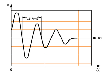
Residual current following operation of a switch.
The striking of HMI lights (both electronic and magnetic) can be a major source of transient over-voltages that can also cause surges in leakage
current. HMI lighting is distinct from other types of lighting instruments in that high voltage pulses are produced deliberately to initiate the
ignition of an arc between the lamp electrodes. These pulses are of short duration, only in the tens of micro-seconds but can be as high as 17,000V.
If the insulation of conductors in the head is even slightly deteriorated, this high striking voltage can generate abrupt current to the equipment
grounding conductor.
Neutral to Earth Shorts:
A particularly problematic fault because of its elusive nature is a short between neutral and earth on a circuit. Since neutral and earth are
nominally at a similar potential, there is typically little current flow between them. However once the neutral current reaches a high enough
level, its potential will be "pulled" away from that of the earth, and the current that flows between them may cause a nuisance trip. Needless
to say this threshold will often be reached during transient current peaks caused by the switching on of equipment with high inrush currents,
such as large incandescent lights (a Tungsten 5k can draw a momentary inrush current of 300A.)

The momentary inrush current of a 5kw Tungsten Light switching on can be as high as 300Amps.
Excessive dust and debris (such as the accumulation of dead bug carcasses) inside a light head can conduct high inrush current to the case ground causing a surge in leakage current. A simple remedy to prevent such current leaks in large Tungsten and HMI lights is to vacuum out the interior of the head. SCR dimmers can be another source of leakage current, especially when the power goes over 3,000W.
The residual currents generated by some lights can be of sufficient magnitude to trip a GFCI without the aid of transient leakage currents. For
instance, the harmonics drawn by non-pfc HMI ballasts can be a large source of residual current. If a HMI ballast is not power factor corrected
it draws a harmonically distorted current waveform. In addition to snubbing the switching noise of transistors to ground, an RF filter will also
snub the high frequency harmonics drawn by the ballast - significantly increasing the residual current generated by the light. For instance, some
non-power factor corrected 1200W HMI ballasts will draw 1.15mA as soon as you throw its breaker to power it up, and an additional 15.32 mA after
you strike the light, for a total residual current of 16.47 mA (which is why these lights are guaranteed to trip inexpensive hardware store style
GFCIs and wall receptacle GFCIs.)
The reason these lights generate such high residual current is that non-power factor corrected ballasts are a type of Switch Mode Power Supply (see simplified schematic below) that first converts the AC waveform of the supply to DC current by means of smoothing capacitors. It then employs IGBTs to switch the DC to a square waveform used to ignite and maintain an arc in the lamp (the purpose of the square waveform is to eliminate flicker appearing on the exposed film.)
A simplified schematic of a non-pfc electronic HMI ballast (Courtesy of Harry Box)
Since its smoothing capacitors only draw current when they charge at the peak of the rectified voltage, the ballast draws a pulsed current consisting of abrupt peaks that are rich in harmonics (see waveform and corresponding FFT reading below.)

The waveform and FFT of current drawn by a 1200W non-pfc electronic HMI ballast
The RF filter snubs the higher frequency harmonics drawn by the ballast to earth, contributing to the additional 15.32mA of residual current measured.
In the waveform and FFT of the ballast's residual current (below) one can see the small amount of mains current inadvertently passed by the filter as well as the harmonic currents it is designed to pass to ground.
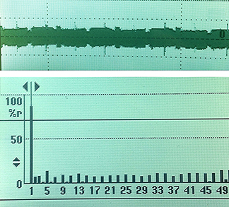
The waveform and FFT of the residual current generated by a 1200W non-pfc electronic HMI ballast
These high frequency leakage currents will cause a hardware store type GFCI to nuisance trip because they do not return via the neutral conductor and so cause the GFCI to see a difference between the current leaving on the hot line and the current returning on the neutral line. It is a nuisance because they in fact pose no hazard.
These high frequency leakage currents do not pose a hazard because, not only are they safely confined to the EGC, but they are also the result of the
system capacitance (the harmonic currents are drawn by the charging of the ballast's smoothing capacitors.) The human body is a resistive load and
according to Ohm's Law (I=V/R) shock current (I) is a function of voltage (V) and resistance (R) only. In this case it is not the residual current that
causes a shock, but the current generated by the resistive value of the individual making contact with the potential to ground. Since the residual
currents do not increase the voltage in the fault circuit there is no increase in shock hazard even though their accumulation on the EGC can cause
nuisance tripping of hardware store type GFCIs.
To avoid GFCIs that have been sensitized by residual currents from nuisance tripping as a result of transient conditions that are not of a sufficient
duration to pose a hazard, in 2003 UL published a new standard (UL 943) for GFCIs designed to prevent nuisance tripping. The new standard allowed GFCIs
to incorporate high frequency filters and trip on an "Inverse Time Curve." Attenuated by a filter, residual currents don't sensitize GFCIs and so pose
less of a problem. An inverse time trip curve permits transient conditions that are sufficiently short in duration so as not to pose a hazard while
keeping current through the body to safe levels. To assure the latter, UL943 requires that as fault current increases the maximum allowable time to
open a circuit and interrupt power decreases, with an almost instantaneous response time required (no more than 20ms) if the fault current is greater
than 300 mA compared to 5.59 seconds at 6 mA. In other words, the higher the current, the faster the GFCI must trip. The advantage of UL943's inverse
trip curve is that it minimizes nuisance tripping from transient conditions while providing protection from shock currents generated by an individual
coming into contact with ground potential.

Relationship of typical GFCI trip curve to the UL943 Curve
Even though UL 943 was meant to enable GFCIs to operate more reliably in real world conditions, manufacturers of lower-priced
Class A GFCIs, like those found on Honda generators and in hardware stores, do not implement the 943 curve because it requires sophisticated micro-processors,
which makes the design more complicated and the GFCI more expensive. Nor, do they filter high frequency residual currents for the same reason.
Instead they use a more aggressive response (like that illustrated above) that is lower and faster than that required by UL 943 (typically 250 ms
at 6 mA where UL 943 permits 5.59 seconds.) The more aggressive response of hardware store style GFCIs is permissible because the UL standard
is the absolute highest current vs. time response accepted but it is not mandatory. That is, a device will fail UL testing if it responds slower
than the standard requires, but will pass as long as the response time is less than the curve time even if it is a lot less. This more aggressive
trip curve does not generally pose a problem in the one-tool per circuit applications for which they are designed. After all, power tools are by
their nature linear loads that do not draw high frequency harmonic currents. However, the more aggressive trip curve of hardware store style GFCIs
has proven to be a problem in applications involving more extensive distribution to multiple non-linear loads, namely the type of distribution that
characterizes motion picture production.

100A Shock Stop GFCI
To prevent nuisance tripping with non-linear lighting loads, Shock Stop GFCIs employ a higher trip threshold and filters to attenuate high frequency harmonic currents. Attenuated by the filter, the noise generated by non-linear loads such Kino & HMI ballasts don’t pose a problem. A higher trip threshold means that residual currents accumulated over multiple loads won’t cause it to nuisance trip.

Shock Stop GFCIs are available with 120V 60A & 100A Bates, as well as 250V 100A Bates (above) and
250V 50A Hollywood Twist-lock configurations (below)

Available with 120V 60- and 100A Bates connectors, as well as 250V 100A Bates connectors, Shock Stops can be installed inline after single and
paralleled generators and our 60-, 84-, and 100A Full Power Transformer/Distros to provide tiered ground fault protection for an entire distribution system. Tiered ground fault protection offers many benefits over the blanket approach described above, especially when it comes to the unusual requirements of motion picture production.

With a 5mA trip threshold, the 50A master GFCI on the Honda EB10000 is prone to nuisance tripping from the accumulated residual currents of multiple loads
A drawback to placing GFCIs on the generator output panel, especially master GFCIs like on the Honda EB10000 pictured above, is that a fault in one
piece of equipment will interrupt power to the entire distribution system. If in a music production that piece of equipment is the digital processor, a
stage will lose all of its’ back line power and the band will go mute. In motion picture production the consequences can be even more catastrophic and possibly even life threatening given the unusual nature of movie production. For instance, imagine the typical indie movie set powered by a portable generator at night. Unlike a road crew working at night, a movie crew uses the ambient light generated by the movie lamps illuminating the set as their work light because separate work lights would pollute the lighting effect the crew is trying to accomplish.
Under such circumstances, should a ground fault occur in a piece of equipment, the entire distribution system will go down leaving the crew figuratively "in the dark" on where the leak occurred while the entire set is literally left in the dark further inhibiting their ability to get the lights back on. And, should the GFCI trip because a crewmember received an electrical shock the darkness will compound the hazard because it inhibits aid being administered to the shock victim. (For this reason, even though NEC 525.23 requires GFCI protection for almost all the 15-, 20-, & 30A 120-volt outlets located outdoors, egress lighting is not permitted to be connected to a receptacle protected by a GFCI.) This example again demonstrates that, while placement of GFCIs on the generator may work adequately in one tool per circuit applications, they clearly do not work in motion picture and event staging applications.

Film style Shock Stop GFCIs can provide tiered ground fault protection on wet hazardous filming locations
A tiered ground fault protection system, like that illustrated above, ensures that only the part of the distribution system affected by a fault will shut down. It accomplishes this by first breaking up the distribution system into zones. Wherever there is a branch circuit, a GFCI sized for the over current device (breaker) is positioned downstream of it. The result is a cascade of interlocking protective zones starting at the power source and ending at the load.
To meet code requirements and avoid nuisance tripping from accumulated residual currents, Shock Stop 100A Lunch Boxes equipped with Class A GFCIs can be
used downstream at the loads. Their 5-20A GFCI protected branch circuits provide the opportunity to horizontally discriminate between loads by plugging
each load into a separate circuit. To provide larger GFCI protected circuits for larger lights, while still avoiding nuisance tripping from residual current
accumulated over multiple branch circuits, 60- or 100A Shock Stops with higher trip thresholds can be used closer to the source of
power.

To meet code requirements and avoid nuisance tripping, the Shock Stop 100A Lunch Box provides
horizontal discrimination by means of five 20A GFCI protected branch circuits.
While interlocking GFCIs with higher and lower trip thresholds in this fashion offers maximum protection against nuisance tripping as a result of
accumulated residual currents, it is still not ideal because in the event of an electric shock all the GFCIs (both the forward and rear) will likely trip and throw the set into darkness – both figuratively and literally. The reason for this is that given the
impedance of the human body, the fault current generated by a shock will exceed even the higher trip threshold of Shock Stops. To assure power
is not interrupted completely in the event of a catastrophic fault, upstream and downstream GFCIs must be discriminated not only by trip threshold
but also by trip time. For this reason, the larger Shock Stop GFCIs can be programmed with a trip delay. By introducing a trip delay in the upstream
devices, it is possible to guarantee that the first and only GFCI to trip in a catastrophic event is the one nearest to the fault, making it
easy for the crew to identify the source of the fault and to correct the problem since they are not in the dark.
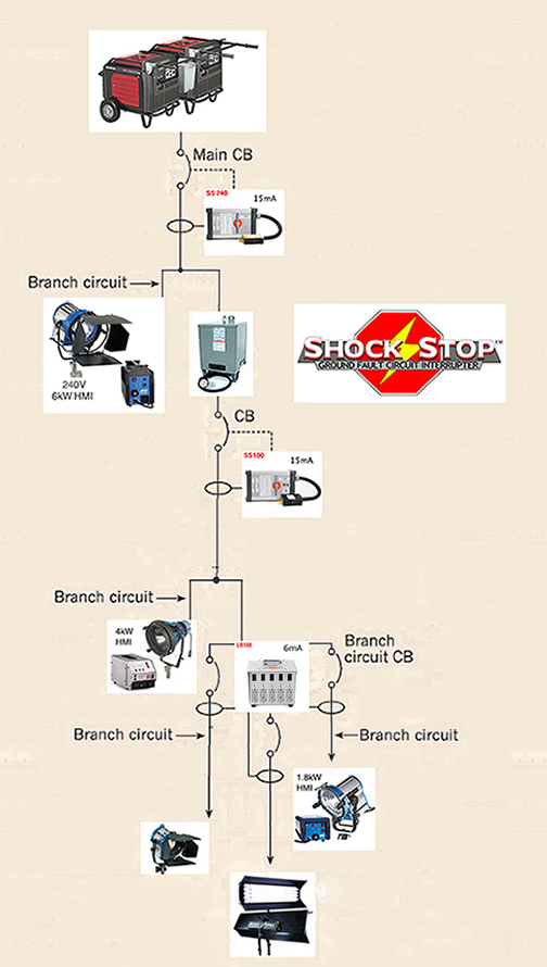
A combination of 120V and 240V Shock Stop GFCIs can provide tiered ground fault protection for set-ups using paralleled generators.
As illustrated above, Shock Stop GFCIs also provide larger GFCI protected circuits than is available on portable generators (by comparison the largest GFCI circuit available on a Honda is only 30 Amps.) In fact, it enables the operation of even 12k HMIs with ground fault protection on paralleled Honda EU6500 or EU7000 generators. Specifically tailored to the type and size loads used in motion picture production, Shock Stops provide reliable ground fault protection for larger lights, or more smaller lights, than has ever been possible on a portable gas generators.

A Shock Stop GFCI with our 60A Transformer/Distro can offer OSHA approved ground fault protection
Shock Stops also incorporate diagnostic features necessary for trouble free ground fault protection on movie sets. To help you avoid unnecessary tripping, Shock Stops feature a liquid crystal display (LCD) that indicates the level of leakage at any given moment. This feature is beneficial in a number of ways. Since almost all electrical devices leak residual current, and these small amounts of leakage can add up to a trip level, it is a good idea to test equipment for leakage current before being used. This includes stingers, lights, cables, or any other equipment that is to be used on set. By monitoring the LCD while plugging and unplugging equipment, an electrician
can discover the amount of current leakage due to a particular load. This way, if a particular load is leaking badly it can be eliminated before the set-up.
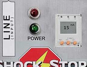
Shock Stops feature a liquid crystal display that indicates the level of leakage at any given moment.
The Shock Stop's LCD will also indicate when the total leakage is approaching the maximum allowed. This way the technician can avoid overloading the Shock Stop
and causing an unnecessary trip that will delay production. Finally, to assure the technician that it is operating properly, Shock Stops include a test function to confirm they will work in the event of a shock. With this level of sophistication, Shock Stops, can provide an unprecedented level of ground fault protection with the Honda EU6500 and EU7000 Inverter generators when used in conjunction with one of our 60A Full Power Transformer/Distros.
Our Full Power Transformer/Distros will also enable you to use film style GFCIs to provide ground fault protection for larger HMIs powered from common 240V wall outlets like range and dryer receptacles. A good example of this approach is an independent film that recently shot in our area that we equipped. The film is loosely based on a “This American Life” radio segment about a family that lived year round in a boatyard because they were fugitives from the FBI because of the father’s drug conviction for raising marijuana. Finding sufficient power to film in the boatyard and on the marina’s docks was a problem for the production because most of the 20A Edison receptacles were equipped with hardware store style GFCIs. This was a problem because they would trip when used to power the HMIs and Kino Flos the production was carrying.

(photo courtesy of Isabelle Landers)
The cart outfitted with 60A Transformer/Distro, 100A Shock Block, and 4/2.5kw & 1800W ballasts that the crew called the E-Cart.
Note: that the 1800W Ballast is plugged directly into a 60A Woodhead w/3 20A circuits.
The solution to their problem was to use one of our 60A Full Power Transformer/Distros to step down the 240V power from a 50A Nema
14-50 receptacle wired into a little shed on the deck of the marina’s guesthouse for the water heater of a hot tub/Jacuzzi. Our Transformer/Distro stepped down the 50A 240V output to a single 60A/120V circuit that was capable of operating not only a 4k HMI Par, but also a 1800W Baby Max. And, because our Transformer/Distros are outfitted with standard film style Bates receptacles,
they could use a film style GFCI that was not prone to nuisance tripping from the harmonics that HMIs and Kinos snub to ground.

(photo courtesy of Isabelle Landers)
The cart outfitted with 60A Transformer/Distro, 100A Shock Block, and 4/2.5kw & 1800W ballasts that the crew called the E-Cart.
As an added benefit, the heavier-gauge Twist-lock cable we use to supply the transformer, eliminated the voltage drop they would have experienced if they instead had run multiple stingers to non-GFCI interior wall outlets to power their 1800W Baby Max. And, the slight voltage boost that we design into our Transformer/Distros assured that the supply voltage on set did not drop far below 120V causing the 1800W ballast to draw more than 19.5 Amps. In fact, the crew was able to run 200’ or more of Twist-lock cable to the cart from the shed without there being an appreciable voltage drop.
Finally, since our 60A Transformer/Distro is compatible with standard film distribution equipment, the crew could use 60A Bates Extensions to run power down to the lights on the docks (breaking out to 20A Edison pockets next to the ballast with 60A Splitters and 60A Snack Boxes), rather than having to run multiple stingers from the ballast back to the Transformer/Distro. By eliminating the line loss from long cable runs, increased resistance from overheated plug ends, and voltage drop in this fashion, our 60A Transformer/Distro assured that both the HMIs and the GFCI operated reliably throughout the production.
To Ground, or not to Ground, that is the Question:
"Whether ‘tis nobler to do it to code at the outset, or beg forgiveness of the inspector in the end"
The National Electrical Code (NEC) is slightly more ambiguous on the question of grounding portable generators than is OSHA. According to NEC Article 250.52 grounding
electrodes (ground rods) are required if the generator is a “Separately Derived System.” What is a Separately Derived System? The NEC in Article 100 defines a Separately
Derived System as:
“… premises wiring system whose power is derived from a battery, from a solar photovoltaic system, or from a generator, transformer, or converter windings, and that has no direct electrical connection, including a solidly connected grounded circuit conductor, to supply conductors originating in another system.“
This makes any generator that is used as a stand-alone power source to supply a film distribution system independent of the location wiring a “Separately Derived System” that requires earth grounding with a ground electrode. The one exception to NEC Article 250.52, is when the conditions of NEC Article 250.34 below are met:
“250.34 Portable and Vehicle-Mounted Generators.
(A) Portable Generators. The frame of a portable generator shall not be required to be connected to a grounding electrode as defined in 250.52 for a system
supplied by the generator under the following conditions:
(1) The generator supplies only equipment mounted on the generator, cord-and-plug-connected equipment through receptacles mounted on the generator, or both, and
(2) The non–current-carrying metal parts of equipment and the equipment grounding conductor terminals of the receptacles are bonded to the generator frame.”
To the conditions of NEC 250.34, OSHA adds “effective bonding of the neutral conductor to the generator’s frame.” This would suggest that not grounding a Floating Neutral generator like the
Honda EU6500is generator does not violate NEC 250.52, it does however not meet OSHA guidelines which require the bonding of Neutral to Ground and the use of GFCIs inorder to float (isolate) the generator from ground.
The use of our 60A Full Power Transformer/Distro with a 100A GFCI satisfies all the criterion of OSHA for the use of a Honda 6500is on job-sites. Does our Transformer/Distro require grounding with an electrode? In the case of Transformers, Section 250.20(D) of the
NEC requires that the grounded conductor (Neutral) on the secondary load side, must be connected to a grounding electrode, when there is no direct electrical connection to the primary grounded
conductor. In other words, because a Transformer, as illustrated below, is also a Separately Derived System, it must be connected to a grounding electrode.

Since as illustrated above, the Neutral on the secondary side of a Transformer is bonded to the equipment grounding conductor, what is the purpose of the Ground Rod? After all, if there was a fault to the equipment grounding system, the Transformer’s circuit breaker would trip eliminating the fault. And, as we saw in the case of Bonded Neutral generators, ground rods serve no purpose in clearing line to line or line to case faults. And, in the case of a Bonded Neutral generator in a Floating Ground arrangement, we saw that an electrical system will operate adequately “ungrounded.” So then what is the purpose of earth grounding the Neutral on the secondary side of a Transformer?
The purpose of the Ground Rod, or more accurately Grounding Electrode System is given in NEC Section 250.4(A) (1) and (2):
“(1) Electrical System Grounding. Electrical systems that are grounded shall be connected to earth in a manner that will limit the voltage imposed by lightning, line surges, or unintentional contact with higher-voltage lines and that will stabilize the voltage to earth during normal operation.
(2) Grounding of Electrical Equipment. Non–current-carrying conductive materials enclosing electrical conductors or equipment, or forming part of such equipment, shall be connected to earth so as to limit the voltage to ground on these materials.”
A historical perspective, offers some added insight why the NEC requires that transformers be earth grounded. Earth grounding transformers was the earliest grounding requirement in the National Electrical Code®, becoming mandatory in the 1913 edition. In that edition of the NEC, the main purpose of grounding (earthing) the system at the neutral of the transformer secondary was to prevent high (primary) voltages from being applied to premises wiring (homes) due to a breakdown of insulation between the transformer primary winding and secondary winding from lightning strikes. In such an event, a primary-to-secondary short would apply thousands of volts to a house, whereby causing an insulation failure in the wiring and a subsequent fire. In other words, the requirement in the Code to earth ground transformers was precipitated by the insurance companies and their concern about large scale fire loss to numerous home owners since the transformers at question serve large portions of the grid.
So, in the final analysis the purpose of the ground rod at a Transformer is to limit the voltage from surges, lightning or unintentional contact with high voltage lines. That is, the only protection
you get from Grounding - actually sticking Mother Earth with a rod - is from lightening strikes or if by some chance a High Voltage line drops down on your generator. Given the chance of either one of these occurrences happening on set, and the subsequent consequences, you
would probably die from the shock of surprise first. But, to adhere to the letter of the Code, you should earth ground the transformer.
The final scenario you are likely to confront is on productions like the shooting of Music Videos, Background Plates, or Title Sequences, that don’t require recording of
sound. In these situations you may well use an “industrial generator” like the Honda EB6500 that has a Bonded Neutral because generator noise is not a consideration. In
these situations neither the NEC nor OSHA require you to earth ground the generator. The reason for this, as we saw above, is that Neutral Bonded generators offer a high
degree of protection against ground faults if they are completely isolated from the earth (if there was a fault to the frame, the generator’s circuit breaker would trip
eliminating the fault)
To isolate a Honda EB6500 from earth requires insulation between all metal points and the ground.
Finally, I am of the personal opinion, that even though OSHA permits the use of the generator frame as ground, and so does not require a ground rod when the system can be effectively isolated from
ground (a Floating Ground arrangement), I think that in the case of Honda portable generators, it is best to earth ground the generator regardless because it is nearly impossible to effectively
isolate a Honda portable generator from earth ground (as the CSAO study demonstrated.) When you think about it, to effectively isolate a portable generator, like the Honda ES6500is, from earth
requires insulating the entire system - generator, distribution equipment, and loads - from earth ground. You must therefore place a rubber mat or apple box, as illustrated above, under any metal
parts of the generator that typically touch the ground. If the generator is on the back of a truck, any type of lift gate or tow chains on the truck must not touch ground. Distribution cable must
be free of cuts or nicks that would expose copper to getting wet. Cable connections must be wrapped so that they are water-tight. Distribution equipment like snack boxes must be placed on apple or
"Swamp" boxes. Finally, light stands must be placed on rubber mats. Even after all that, as the CSAO study illustrated, portable generators, like Hondas, can still be inadvertently grounded by moisture
and even high humidity. Where that is the case the protection afforded by using a Floating Ground arrangement is precarious at best, and since the NEC Article 250.52 requires a grounding electrode
system be installed if complete insulation is not possible, it makes sense to ground your system regardless.
1) Current goes out on the hot (black conductor) to the light housing fault.
2) Even though current travels on the ground wire (if it is in good condition), current also
travels through the worker's body into the earth back to the generator windings, because there
is no clear return path because of the un-bonded condition.
3) Current enters the generator frame and goes back to the generator winding through the second Fault
on the Neutral side. Because the impedance of the ground rod limits the Fault current it passes, the current
will not be high enough to open the breaker.
4) But, since the ground rod creates a circuit for the ground fault to return to the generator winding
through the second fault, the Fault current goes to ground, creating the imbalance between Hot & Neutral
requird to trip a GFCI if it were present. Unfortunately, for this poor soul there was no GFCI.
Even though a ground rod will not pass enough current to activate an over-current device, (as illustrated above) grounding generators to earth offers some degree of protection from electrical shock
in the event of a double ground fault – it is for this reason that it is mandated by OSHA in the event that the power system cannot be effectively isolated from earth. When the equipment grounding
conductor is earth grounded with a grounding electrode, the equipment grounding conductor offers a path of lesser resistance then the individual/ground route for the current to travel back to its’
source through the second fault. As the figure of the Utility Line-men above illustrates, the individual making contact with the energized housing will receive a lesser shock, because some of the
fault current will travel through the equipment grounding wire instead. And, because of the voltage split that results from there being two ground paths, the individual will receive less of a
shock than if there were only one. Finally, since the ground rod creates a circuit for the ground fault to return to the generator winding through the second fault, the Fault current will go
to ground, creating the imbalance between Hot & Neutral required to trip a GFCI if it is present. So, in the final analysis, in the case of small portable generators, like Hondas, I think
it is best to ground in all situations even though OSHA permits you not to in some. But, in the end, the AHJ (Authority Having Jurisdiction) is the ultimate authority for what practices will be
allowed on set. The AHJ, depending on where the work is taking place, may be the local city electrical inspector, the fire marshal, or the studio’s safety officer.
Harmonic Mitigation
While transformers can offer many benefits, certain features are required in a transformer to make it suitable for motion picture production. If the transformer is going work close to set as a load bus (distribution panel), a principle requirement is that it operate silently. Traditional air cooled Open-Core Design Transformers in Nema 1 enclosures, like the one pictured below, are ill suited for production work for a number of reasons – the noise they generate primary among them.
Like all transformers it consists of two coils called windings wrapped around a core. A transformer works when a source of AC voltage is connected to one of the windings and a load device is connected to the other. The winding connected to the source is called the Primary. The other winding, which is connected to the load, is called the Secondary. In a step down transformer,
the Primary is wound in layers directly on a rectangular form. The wire is coated with varnish so that each turn of the winding is insulated from every other turn. When the primary winding is completely wound, it is wrapped with insulating paper. The secondary winding is then wound on top of the primary winding. After the secondary winding is done, it too is covered with insulating paper.
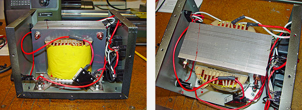
Open-Core Transformer Design
If you look at the transformer in our HD Plug & Play package (pictured below) you will notice it looks quite different from the Open-Core Design pictured above. For our HD Plug & Play package we use an Epoxy Encapsulated-Core Design Transformer. Epoxy encapsulated transformers use a mixture of silica sand resin and epoxy to completely encapsulate the transformer in a heavy gauge steel casing. Their steel cases are welded and treated with conversion coating before priming and painting to withstand the harshest elements.
Encapsulated transformers offer a number of advantages over open-core designs. The most obvious benefit arises from the physical protection that the encapsulate and outer steel casing provide to the windings, core, and lead connections. With these fragile components sealed in epoxy inside a tough, waterproof casing, encapsulated transformers will withstand the harshest indoor and outdoor applications - making them the clear choice for exterior location production.

Encapsulated-Core Transformer
However, physical toughness and environmental ruggedness are not the only advantages. Constructed of a welded heavy gauge steel casing filled with epoxy, an Encapsulated Transformer forms a single solid mass with no moving or loose parts that can vibrate. Encapsulating the transformer significantly reduces its’ audible noise – an important feature in motion picture production.
The most important benefit to encapsulation, however, is the improvement to the thermal and electrical performance of the transformer that results. Encapsulation greatly improves the transformer’s K-Rating. What is a K-Rating?
It is a value used to determine how much harmonic current a transformer can handle without exceeding its’ maximum temperature rise level. Encapsulation is a design element K-rated transformers use to deal with the heat that harmonic generating loads create – an increasing problem in motion picture production today.
As discussed previously, there has been dramatic growth in the use of production equipment that generates harmonic distortion over the last several years. Examples are the AC power supplies of video cameras, lap top computers, video display terminals, battery chargers, and electronic lighting ballasts (HMI & Kino.) These electronic devices contribute to the distortion of the current waveform and the generation of harmonics because they use switching power supplies called SMPSs (an abbreviation for Switch-mode Power Supplies.) SMPSs generate harmonics when they rectify AC line current to DC, and back again in supplying current to the load. In the process, a capacitor is charged then discharged in each half-cycle of the AC line current. This process is repeated 120 times a second. This action of recharging capacitors causes AC current to flow only during the peak portion of the AC voltage wave, in abrupt pulses. These abrupt pulses distort the fundamental wave shape and create harmonic currents, which in turn generate heat in distribution equipment and neutral conductors. Harmonics can cause distribution transformers to heat up considerably because the harmonics cycle in their Primary windings. The heat harmonics generate can cause non-K-rated transformers to overheat - possibly causing electrical insulation failure and electrical arcing. K-rated transformers are designed to handle this additional heat and are tested to rigid UL standards. Design features K-rated transformers use to handle the adverse effects of harmonics is double sized neutral conductors, multiple conductors for the coils, more core and coil material, different designs, and different construction techniques like epoxy encapsulation.
Encapsulation is used in K-rated transformers because it greatly improves thermal and electrical performance and consequently the transformer’s K-rating. The mixture of silica sand resin and epoxy compound used for potting has a high coefficient-of-thermal conductivity and is very effective at dissipating heat away from the windings and core; while the heavy gauge steel casing serves as a heat sink. This thermal management reduces winding temperature differentials and allows for the generation of more heat without exceeding allowable temperatures for the insulation class.
Besides causing equipment to overheat, Harmonics can cause device malfunctions, breaker tripping, and excessive vibration. Harmonic
currents cycling inside the primary of the transformer can cause Open-Core transformers to vibrate and hum loudly. Epoxy encapsulation
dampens the vibration and significantly reduces the hum created by cycling harmonic currents. Encapsulation also increases electrical
insulation reliability when compared to tape or paper insulation. Potting is done under vacuum to eliminate air gaps around the windings.
With no air around the windings, there is reduced potential for corona and electrical arcing under surge conditions. Even though,
K-rating is a heat survival rating, not a treatment of associated power quality issues like voltage distortion, encapsulation can
reduce harmonic losses to a slight degree as well.
Transformer/Distros verses Splitter Boxes
Since Honda manufactures their super quiet generators primarily for the RV/Home Standby Power markets, and not the film lighting market, lighting rental houses have had to find ways to work around the limited power
distribution panel that Honda puts on their generators. For years rental houses have wired custom distribution panels, called “Splitter Boxes,” in order to access more 120V power from the 240V twist-lock receptacle on
the generators. While this approach worked well enough when the lighting load placed on generators consisted predominantly of incandescent lights (a linear load), Splitter Boxes are inherently unsuitable to carry a
non-linear loads consisting predominantly of non-Power Factor Corrected HMI, Fluorescent, & LED Lights. For this reason, Splitter Boxes should not be used on the new 10kW Honda EB10000W even though it offers enough power
on each of its' legs (42A) to power large HMIs. To understand why this is the case, we must first appreciate why 240V circuits are provided on the generators in
the first place (it is not to power our lights) and how they work.
Honda EB10000 Generator with 84A Full Power Transformer/Distro
240V outlets are on generators to power common residential or industrial single-phase 240V loads. The most common are air conditioners, dryers, ranges, heaters, large motors, and compressors. If you look
at the breaker of a 240V circuit on a building service panel that serves these loads, you will notice that they use two pole breakers - either 30A or 50A. Each pole of the breaker is in a sense an
independent 30A or 50A 120V circuit. That is, if you measure the voltage from each pole of the breaker to ground it will be 120 volts, and if you measure the voltage between the two poles of the breaker
you will notice that it is 240 volts. As illustrated below, the 120 volts of the two poles adds up to 240V because the 120V circuits are on opposing legs of a single phase service and 180 degrees out of phase with each other.
In residential settings, this is how higher voltages are supplied to household appliances like Dryers, Electric Ranges, Air Conditioners, as well as Motors, etc. that require more power than can be
reasonably supplied by a single 120V circuit.
The voltage of opposing legs of a single phase circuit add while the current carried on the legs subtract.
Many of these household 240V receptacles, in fact, use a three-wire system (Hot, Hot, Ground, but no Neutral) because they are designed to power single phase loads (compressors or heating elements) that draw a perfectly balanced
load and hence return no current. As you may recall from our previous discussion, the current drawn on the two legs of a perfectly balanced single-phase 240V circuit cancel each other out because they are 180 out of phase.
Other 240V circuits use a 4 wire system (Hot, Hot, Ground, Neutral.) They include a single Neutral wire to provide a safe return for small 120V accessories in stoves and dryers like oven lights, clocks, and timers that throw
off the balance. There need be only one Neutral wire for the two Hot wires because under normal applications the current on the Neutral is the difference between the Hot legs because of the phase cancellation. Since oven
lights, clocks, and timers don’t draw much power, there is minimal current to return on the Neutral under normal applications. For this reason, the Neutral wire is typically the same size as that of the hot legs
(remember the heating element of the stove/dryer operates a perfectly balanced single phase load and hence there is no return for the wire to carry from it). To service these same residential and industrial 240V loads, the
240V receptacles of portable gas generators are wired in a similar fashion with just one Neutral of the same size as the two hot legs (see wiring schematic below).
Generator Wiring Schematic
A "Splitter Box" works around the limitations of the generator power output panel, and provides additional 120V circuits, by splitting out the two 120V circuits that make up the 240V outlet. For the purpose of this discussion,
it is important to understand that Splitter Boxes are wired so that their 120V circuits share in the single Ground and Neutral of the 240V circuit. Splitter boxes worked well enough back when the load on the 240V circuit
consisted of only incandescent lights. As long as you roughly balanced your load between the two legs of the generator, phase cancellation between the legs resulted in the Neutral return being the difference between the legs.
As we have seen, things get a bit more complicated with inductive (magnetic HMI ballasts) and capacitive (electronic HMI, Kino, & CFL ballasts) non-linear lighting loads.
Since non-linear loads cause current and voltage to be out of sync, the phase currents no longer entirely cancel when they return on the Neutral. In addition to pulling the voltage and current out of phase, the Switch Mode Power
Supplies of electronic lighting ballasts create harmonic currents that stack on top of one another, creating very high currents returning to the power source on the Neutral wire. As discussed previously, the “triplen” harmonics
(i.e. 3rd, 5th, 7th, 9th, etc.) are particularly troublesome because when the triplens of each phase of the distribution system are dumped into the Neutral return, they are all in phase with each other. For this reason, rather
than cancel each other out on the Neutral conductor, as the out of phase fundamentals do, they instead add up. If the lighting package consists entirely of non-linear light sources without power factor correction, as much as
80 percent of the current will not cancel out between legs, resulting in very high current on the Neutral return even when the legs are evenly loaded. For this reason, on their website Kino Flo cautions users that some of their
lights “will draw double the current on the Neutral from what is being drawn on the two Hot legs... it may be necessary to double your Neutral run so as not to exceed your cable capacity.” ( FAQ “Why is the neutral drawing more than the hot leg”.)
Before attempting to use a Splitter Box on a Honda EB10000, it is important to appreciate the potential hazard that the harmonic currents generated by SMPS stacking on the Neutral can pose. If you will recall from the study cited above (illustrated below), the combined effect of the phase
shift and harmonics generated by substituting incandescent lamps with an equivalent wattage of CFLs resulted in more than a doubling of the current on the system Neutral.
Substituting a linear load with a equivalent non-linear load
in a small single phase distribution system substantially increases the current on the system neutral.
Since there is no over-current protection on the Neutral of a 240V circuit, these currents can lead to overloading of the Neutral and a fire like the one that occurred in Vice President Dick Cheney's suite of offices in the
historic Eisenhower Executive Office Building next to the White House on December 19, 2007. The cause of the fire that started in an electrical closet on the building's second floor, was found to be caused by an over-loaded
Neutral wire that resulted from uninformed staff replacing all the incandescent bulbs in the complex with CFLs.
There is no question that we find ourselves in an analogous situation, since light sources that use Switch Mode Power (HMI, Fluorescent, & LED) have almost entirely replaced incandescent lights as the prevalent lighting source
in HD Digital Cinema production packages. To make matters worse, the video cameras, field monitors, hard-drives, lap-tops, and battery chargers that make up the typical location production package also use Switch Mode Power
Supplies and hence generate their own harmonics. Where just about every piece of production equipment used on set today generates harmonics, the current returned on the Neutral system can be quite high. For example, if say the new 10kW
EB10000 were loaded to its’ continuous load rating of 9000 Watts with a typical digital cinema production package (consisting predominantly of non-linear loads like video cameras, field monitors, battery chargers, lap tops,
hard drives, non-PFC HMI, LED, and Fluorescent lighting fixtures), as much as 60 Amps can be returned on the Neutral wire (Apparent Power Load of 9000W/120V= 75A x.8 = 60A) even when the legs are perfectly balanced. And, where
it is nearly impossible to perfectly balance a load on a splitter box (it requires meticulous attention to loads as you plug in) the return of the Neutral is likely to be even higher because of an unbalanced load. Since there
is no over-current protection on the Neutral of a 240V single phase circuit of a generator (see schematic above), and the wire used in the 240V receptacle of a Honda Generator is only rated for 50A, these currents can likewise
lead to overloading of the Neutral.
In this new world of Switch Mode Power, older power generation and distribution systems, like AVR generators and Splitter Boxes, are simply no longer capable of managing the adverse effects of the harmonics that SMPS generate.
The 240V circuits they use were designed, not for harmonic generating non-linear loads, but for single phase linear loads like dryers, ranges, heaters, large motors, and compressors, that draw a perfectly balanced load and
return no current on the system Neutral. Because under normal application there is no situation where you would draw more amperage than could be supplied by one leg of the circuit, the Neutrals of 240V circuits are sized to
carry no more than the return current of just one of the individual 120V hot legs of the circuit. The Neutral wires of 240V receptacles on portable gas generators like the new Honda EB10000 are simply not sized to handle the higher return
current generated by loads that stack on the Neutral rather than cancel out. Splitting the 240V circuit designed into the EB10000 to power primarily heating elements and compressors, to instead power field production equipment and motion picture
lights is an application for which this circuit was simply not designed.
In this discussion it is important to understand that harmonic currents will stack on the Neutral return regardless whether power is being generated by an AVR or Inverter generator. The nearly pure power waveform and low
impedance of Inverter generators results only in harmonic currents not distorting the voltage waveform. It does not mean that harmonics will not be generated. The harmonic currents generated by Switch Mode Power Supplies
will stack equally on the Neutrals of AVR generators and Inverter generators and have the same adverse effect – over heating of their Neutral bus.
Overheating of Neutrals as a result of high harmonic lighting loads happens on all levels of production. There was a case recently reported on a
Cinematography.com where the Neutral of a distribution system burned up even though the load
(which consisted of 2-18ks, 2-12ks, & 2-4ks) was perfectly balanced. For this reason, it is a standard practice on large film sets when powering large numbers of electronic ballasts to size the Neutral feeder of
the distribution system to carry the sum of the currents of the phase legs times the 80 percent (.8). If power is coming from a generator, the generator is likewise oversized to handle the higher return current without its
Neutral bus overheating. Where these are not options on small film sets using portable gas generators like the Honda EB10000, other measures must be taken. When using a splitter box, the only option is to de-rate the
generator so that you never load it to more than 60% of its “Continuous Load” Rating.” A safer and more reliable option is to use a step-down Transformer/Distro on the EB10000 instead of a Splitter Box.

A sunny feel is created on an overcast day by a Honda EU6500is powering a 4kw HMI Par and a 1800W ArriMax for a commercial.
Since a transformer, like a generator, serves as an new impedance point in a power system, it in effect separates the power generation system (the primary side) from the power distribution system (the secondary side.) In our HD Plug-n-Play
system, we take advantage of this fact and use a transformer to isolate the generator from the high Neutral returns generated by SMPS. To mitigate the adverse effects of harmonics on the secondary side, we use “K” rated
transformers and beef up the Neutral in the distribution system.
For example, we outfit our 60A Full Power Transformer/Distro with the industry standard 60 GPC (Bates) receptacle, so that you can use standard 60A GPC extension cables, 60-to-60 Splitters,
and fused 60A GPC-to-Edison Breakouts (snack boxes) to run power around set - breaking out to 20A Edison outlets at convenient points (rather than one central point.) In this secondary distribution system the Neutral has the
same current carrying capacity as the now single current carrying wire. Since the current carrying capacity of the Neutral is now 60 Amps verses the 30 amps of the generator 240V twist-lock receptacle, harmonic currents
stacking on the Neutral will not overload it (likewise for our 84A Full Power Transformer/Distro on the Honda EB10000.)

A sunny feel is created on an overcast day by a Honda EU6500is powering a 4kw HMI Par and a 1800W ArriMax for a commercial.
What happens to the harmonic currents returned on the Neutral of the secondary distribution system? They cycle inside the transformer. For that reason, in addition to using a beefed up Neutral return in our distribution system,
we use transformers that are “K-rated.” As you may recall from our discussion above, K-rated transformers are designed to handle the additional heat generated by harmonic currents. Through such design features as double sized
Neutral conductors, multiple conductors for the coils, more core and coil material, epoxy encapsulation, and vacuum construction, K-rated transformers, unlike Splitter Boxes, effectively manage the heat generated by harmonic
currents and therefore allow for the generation of more heat without exceeding allowable temperatures for the insulation class.
Effective management of the heat generated by harmonic currents on the secondary side, is only half the story of how transformers mitigate the adverse effects of harmonics in a power generation and distribution system.
The other half of the story is that, in their design and construction, transformers separate the power generation system (the primary side) from the power distribution system (the secondary side) so that harmonic currents
returning on the Neutral conductor of the secondary distribution system are isolated from the generator – they simply do not make it back to the generator Neutral bus. If you recall from our discussion above, the primary windings
are physically separated from the secondary windings in the construction of the transformer. The load placed on the secondary windings is transferred through electro-magnetic induction to the primary windings, but not the
Neutral return current – it cycles inside the transformer (hence the need for effective heat management on the secondary side.)

A sunny feel is created on an overcast day by a Honda EU6500is powering a 4kw HMI Par and a 1800W ArriMax for a commercial.
But, that is not the whole story. With a two to one ratio between the number of wire turns in the primary windings verses the secondary windings, a step-down transformer evenly splits the load placed on the secondary between
the two 120V single phase legs of the transformer‘s primary or power generation system. Where the two 120V legs of a single phase generator, like the EB10000, are 180 degrees out of phase, the perfectly balanced load cancels out on the primary
side and there is no Neutral return on the primary side or power generation system. In fact, the high voltage three conductor wire that we use between the generator and the transformer has no Neutral conductor. Since, there
is 100% phase cancellation between the two perfectly balanced legs on the primary side, there is simply no need for a Neutral return in the power generation system (as opposed to the power distribution system on the secondary
side.)
It is important that you understand that a conventional transformer only isolates harmonic currents returning on the Neutral wire from returning to the generator’s Neutral bus.
The harmonic currents drawn by non-linear loads will still create voltage waveform distortion when it encounters the impedance of the generator and cable supplying it. For this reason,
if your load is predominantly non-linear, it is important to use a low impedance inverter generator like the EU6500is, instead of an AVR generator like the EB10000.
Honda EB10000 with Voltage Select 84A Transformer/Distro
and 14 Gallon Fuel Caddy
Besides providing effective management of the higher Neutral return currents generated by SMPS, a Transformer/Distro system offers a number of other benefits (covered above) that Splitter Boxes do not. Unlike a 240V "Splitter Box,"
where you have to meticulously balance your load, a Transformer/Distro greatly simplifies your set electrics by automatically splitting the load evenly. The best part about using a transformer as a distro is that no matter where in
the secondary distribution system you plug in, the transformer automatically balances the additional load. Part of the reason the generator in our HD Plug-n-Play Pkg. is capable of handling a larger load is because it is a
perfectly balanced load. Another benefit discussed previously, but worth highlighting here, is that a Transformer/Distro converts the 240 volts supplied by the generator back to 120 volts in a single circuit that is the sum
of the two single phase legs (60A/EU6500is, 84A/EB1000.) This new 120V circuit not only makes the generator capable of powering more small luminaries, but also bigger ones, than it could otherwise (a Splitter Box on the
EB10000 won't reliably power a 5k, while a Full Power Transformer/Distro on the same generator is capable of powering a 9kw Maxi Brute.) And, since the transformer automatically
splits the load of whatever you plug into it evenly over the two legs of the 240V circuit, you can stack the generator more fully. Finally, by adjusting the ratio of the primary to secondary windings, our Transformer/Distro
slightly boosts the output on the secondary side, which compensates for line loss over long cable runs. This means that you can operate our
Transformer/Distro substantially further from the generator than you could a Splitter Box (a necessity with the EB10000.) The greater distance possible between the generator and the Transformer/Distro makes it more likely that
you will be able to operate the generator from around the corner of a building, or out of the back of a truck, where you will not pick it up in your audio tracks. These are just a few of the many benefits our Full Power Transformer/Distros offer that Splitter
Boxes do not.
Enables the Paralleling of the Honda EU6500 and EU7000 Generators for 100A and 120A Output
Our 100 Paralleling Control Box for the EU7000is provides 100A output
and load sharing control to optimize the output.
The biggest impediment to paralleling two Honda EU6500s or EU7000s for motion picture lighting is "cross current" that circulates continuously
between the generators that can cause their inverters to overheat and fail. A primary source of this cross current is the harmonic current returned on the
neutral by out of balance 120V non-linear loads. For this
reason, Honda restricts the loads to be powered by their paralleling box to 240V single phase loads that will return no current on the common
neutral. One of the most important benefits to be gained by using a Transformer/Distro in paralleling operation is that it makes it possible to
power 120V non-linear loads on paralleled generators without elevating their cross current. It does so by isolating the generators from high neutral
currents generated by 120V non-linear loads that can lead to over heated conductors, coils and inverters as they circulate continuously between the generators
as cross-current.
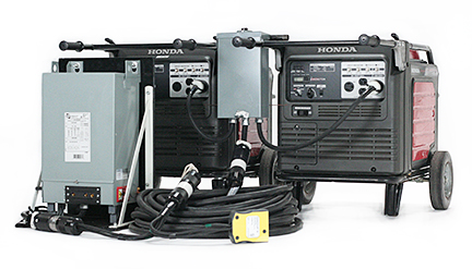
Parallel operation of two Honda EU6500 generators made possible by
our new Paralleling Control
Box
A complete paralleling system consists of two Honda EU generators (either 6500 or 7000), a more advanced paralleling control box (than what Honda offers), and one of our
Transformer/Distros (either 60-, 84-, 100 Amp.) To understand the role of each component of the system, let’s take a quick look at some of the
issues involved in paralleling generators before we get into the details of how to parallel the single-phase Honda EU generators.
Overview:
When two generators are operated in parallel, a current will circulate between the generators. This current exists because the internal voltage generated by each generator is slightly different from the other, but the terminal or bus voltage is the same. As illustrated below, this current flows through the entire system because paralleled generators have their neutral buses connected, either directly or through an earth or ground connection. This current, called "circulating current”, or “cross current” is in addition to the normal line current drawn by the connected load.
Generators in paralleling operation with very dissimilar voltages can readily experience cross current equal to 20%-25% of their ampere rating with no-load (zero kilowatts) on the generators. We are concerned with these "watt-less amperes" because they can interfere with normal operation. For example, since the circulating cross current is superimposed on the load current passing through the generators’ circuit breakers, cross current can cause a breaker to trip unexpectedly as the breaker "sees" the actual combined amperes and not just that drawn by the load. Observed line current (as indicated by panel ammeters in a parallel generator system) is then a summation of two or three currents:
1. Load current - that current which is drawn by the load. As we have seen, it can be linear and in phase with the voltage (a unity power factor), or it can be non-linear and out of phase with the voltage (power factor less than unity).
2. Circulating cross current - the current described above which flows between generators for reasons we will explore in more detail below.
3. Harmonic current - the third harmonic component of the cross current as well as the harmonic currents drawn by any non-linear loads.
Another cause of concern in paralleling operation is that each of the above currents contributes heat to the generators’ conductors, coils and inverters. Since, as is evident in the illustration above, cross current passes through the generator coils, these currents heat the coils the same as does the load current. In the case of the 60 Hz Fundamental component, the amount of heat loss being equal to the square of the sum total of the 60 Hz Fundamental current times the resistance of the coils. Thus, if the 60Hz current is doubled by the superimposition of the cross current, the heat loss increases by a factor of four. If the generators are supplying power to non-linear loads, the amount of heat generated is even more severe. Severe coil heating will lower efficiency and possibly even cause a breakdown of the insulation between the Stator’s windings.
Voltage adjustment and proper power distribution can reduce cross currents (both the Fundamental and Harmonic) to a minimum. Given the potentially dire effect cross currents can have on generators operating in parallel, understanding their origin and how to mitigate their adverse effects is paramount to the successful operation of two generators in parallel.
Basic Concepts:
To see how this is the case we must first review some concepts we covered earlier.
The voltage waveform shape created by a generator is not an ideal sinusoid and no two machines are the same. Furthermore, as we have seen above, its' shape is also affected by its' load. The resulting waveform may be described in terms of its fundamental frequency and voltage magnitude and the magnitude of the harmonic voltages and their frequencies that make it up. This harmonic voltage distortion, while small in the case of inverter generators, may still be significant, particularly in paralleling applications.

(Harmonic Content of a Generator's Voltage Waveform)
The illustration above shows the relationship of first-order (Fundamental frequency waveform) to third- and
fifth-order harmonic waveforms of a slightly distorted waveform. The harmonic voltages are effectively added to the fundamental
waveform, resulting in the pure sinusoidal shape of the fundamental being somewhat distorted. For example, the resultant
voltage at time A in the figure above will be the sum of the blue (fifth-order), green (third-order), and red voltage
magnitudes. So, the instantaneous voltage at that instant in time would be somewhat higher than the voltage of the
fundamental.
When generators are paralleled, the voltage of the two machines is forced to the exact same RMS voltage magnitude at the
common load bus. Differences in the harmonic make up of the voltage waveforms result in the cross current flowing in the
common conductors of the two machines even when there is no load. Its’ source is illustrated below:

(How 3rd Harmonics are generated)
In this illustration, two voltage waveforms of the same RMS value (the red and blue lines) are superimposed
upon each other. Note that even though these voltage waveforms have the exact same RMS magnitude (they would read the same
on a true RMS meter), at different points in time the blue voltage is higher than the red, and vice versa. Since there exists
potential (voltage) between the two machines at these points, when the machines are connected together on a common bus,
current will flow between the machines (cross current) even if there is no load. Note that because the blue and red voltage
lines cross each other three times in each half cycle, the cross current includes a 3rd harmonic component (this current is
represented by the green line.) And, because the conductors of the two machines are tied together, this cross current will
continuously circulate (as illustrated below) between the two generators. If we trace this current in the illustration below,
we see that it flows out the line leads of one generator, through the neutral paralleling bus and into the second generator.
It does not flow into the load.
The Make Up of Circulating Cross Currents
The process of mathematically deriving the frequency components of a distorted periodic waveform is achieved
by a technique known as a Fourier Transform. Microprocessor based test equipment, like the power quality meter pictured below,
can do this mathematical analysis very quickly using a technique known as an FFT (Fast Fourier Transform) which it displays as
a bar graph. Each bar represents the magnitude of a harmonic frequency, be it voltage or current. Below is a power quality
meter reading of the cross current that circulates on the neutral between two Honda EU7000s operating in parallel mode with
no load. The FFT for this cross current reveals that there is roughly 6 Amps of current, with a significant 3rd harmonic
component even under ideal conditions (inverter generators operating at the same voltage).

(The 3rd Harmonic Content of neutral cross current with no load.)
This no-load cross current can become a problem if we add to it the harmonics dumped into the neutral by
non-linear loads such as non-power factor corrected HMIs, Kinos, & LED lights. Because some of these harmonic currents
(the load generated 3rd harmonic and the 3rd harmonic of the cross current) are in fact in phase with one another they
do not cancel in the neutral as the Fundamentals do, but instead build one on the other to create elevated cross current
with a large 3rd harmonic component much like the triplens do in the
neutral of 3-phase systems - but unlike triplens in a 3-phase system, these 3rd harmonic currents circulate continuously
on the generators' conductors. And, because this elevated 3rd harmonic cross current is at a higher frequency (180Hz) than the
Fundamental it generates a lot more heat (9x more), contributing significantly to the overheating of the common conductors of
paralleling generators and especially to the inverters of paralleling Honda EU6500s and EU7000s (more on this latter.)
Our Particular Problem
Other industries that parallel generators (industries like sound reinforcement for events) typically do not
have a problem even though their loads consist predominantly of non-linear amplifiers, consoles, powered wedges, and LEDs (while some high power amplifiers use PFC Switch Mode Supplies, audio power amps have pretty much dodged that regulatory bullet so far.) The reason for their success, even with dirty loads, is that their non-linear loads tend to be many and small in size and so balance each other out when distributed over the balanced legs of single-phase generators operating in parallel. Unfortunately, that is not always the case in motion picture lighting – especially when it comes to the segment of the market paralleling single phase Honda inverter generators.
The segment of the motion picture production industry using Honda generators as their primary source of set power (regional commercial spots,
historical documentaries, and indie films), quite often are using them to power just one big light while they plug all their small lights
into the location house power. The go to fixtures in these segments of the market are HMIs ranging from 1.2 to 4kw. In this country the
majority of HMIs in this range are not power factor corrected (as they are in Europe) and so they draw significant harmonic currents. For
example, the power quality meter readings below are the distorted voltage and current waveforms created by a 4k HMI with non-PFC ballast
operating on an EU6500 and their corresponding Fourier Transforms (note that the individual harmonic currents encountering the impedance
of the generator cause voltage drop at the peak of the voltage waveform creating harmonic voltages at the same frequencies as the harmonic currents drawn by the load.)

(L-to-R: Test Set-Up, Distorted Voltage (top) and current (bottom) waveforms, Corresponding
Fourier Transformations (Voltage left and Current right)
These low budget productions quite often compound the problem presented by the harmonics generated by large
non-PFC HMI lights by operating them on a single leg of a “Splitter Box.” A Splitter Box (pictured below) works around the
limitations of the generator power output panel, and provides additional 120V circuits, by splitting out the two 120V circuits
that make up the 240V outlet. Splitter Boxes worked well enough back when the load on the 240V circuit consisted of only incandescent
lights. As long as you roughly balanced your load between the two legs of the generator, phase cancellation between the legs resulted
in the Neutral return being the difference between the legs and without a harmonic component. Things get a bit more complicated with
non-linear lighting loads, especially in paralleling applications.

The Splitter Box pictured above breaks out the 240V power of a generator
into two circuits
with film style “Bates” receptacles as well as Edison receptacles
As discussed previously, harmonic currents (particularly the 3rd) are troublesome. When they are dumped into the return of even a balanced single-phase distribution system, they do not entirely cancel and in fact add to the 3rd harmonic component of the no-load cross current that circulates continuously between the generators. And, when the load includes a large non-PFC HMI fixture that throws the system out of balance, the 3rd harmonic component contributed by the load, on top of that inherent in the no-load cross current, can result in cross current with a severely elevated 3rd harmonic component circulating between the generators.
Practical Demonstrations
I can’t demonstrate what would happen if one ran paralleled generators in a severely out of balance condition by operating the non-pfc 4k HMI mentioned above on one side of a single phase Splitter Box because I don’t have a Splitter Box that is large enough. But, I can give you an idea of what would happen by running smaller linear and non-linear loads on one side of a smaller Splitter Box.

(Note the yellow “Splitter Box” on the left provides only two 20A circuits from a 30A/240V receptacle.
By comparison our 60A Transformer/Distro provides the 3 – 20A circuits of the gang box
and a 60A receptacle from the same
30A/240V receptacle)
Using the set-up pictured above, let’s compare the cross currents circulated by two common loads
(a 2kw quartz Fresnel and a non-pfc 1.2kw HMI) under two different situations: when power is supplied by a
Splitter Box with a common neutral (the yellow distro box on the left in the picture above) and when it is supplied
by a step-down transformer (the gray box on the hand-truck supplying the 60A gang box on the right side of the picture above.)

(The 3rd Harmonic Content of neutral cross current with no load.)
As you can see in the power quality meter reading above, in this case there is 2.08A circulating between the
two machines on a continuous basis even without a load. Of that 2.08 Amps nearly a quarter of it (.39A) consists of 3rd
harmonic current. As you can see in the picture below, powering a 2kw Quartz Fresnel by means of a Splitter Box does not
add to the 3rd harmonic content of the cross current because it is a linear load that draws no harmonic current.

(The 3rd Harmonic Content of cross current is not increased
by the addition of linear loads like our 2kw Quartz Fresnel)
But, as is evident in the power quality meter reading below, it is an altogether different situation when the paralleled generators are powering a non-power factor corrected 1.2kw HMI. Even though the 1.2kw HMI draws roughly the same current as the 2kw Fresnel, because it is a non-linear load that draws current harmonics, it adds an additional 4.11 Amps of 3rd harmonic current to the continuously circulating cross current.

(Powering a non-PFC 1200W HMI by means of a splitter box increases the 3rd Harmonic current
circulating between the two generators by a factor of 150X.)
This 3rd harmonic content drawn by the 1.2kw HMI is problematic because it does not cancel with the no-load 3rd harmonic of the cross current generated by paralleling the generators. Where before, with a linear load, the 3rd harmonic made up 4% of the current circulating on the combined neutral, with the contribution of the 1.2kw HMI, the 3rd harmonic makes up nearly 60% of the current.

3rd harmonic component of the the neutral current generated by 1.2kw HMI on a single EU6500 (left)
and on paralleled EU6500s (right)
How do we know that the 3rd harmonic component of the cross current is being superimposed on top of the 3rd harmonic drawn by the 1.2kw HMI. If we compare the distribution of harmonics drawn by the 1.2kw HMI on a single EU6500 (above left) to that drawn by the same light on paralleled EU6500s (above right), we see that the percentage of the total amperage that is the 3rd jumps from 56.9% to 59.6% when the light is powered by the paralleled EU6500s. In this situation, with just the one light running on each source, there is only one possible source for the additional 2.7% of third harmonic current to come from: it can only be the 3rd harmonic component of the circulating cross current (we can’t compare the actual amperages of current in each situation because the current is split between two generators in the paralleling situation.) Because a greater percentage of the elevated cross current is of a higher frequency, it generates more heat (more on that latter.)

3rd and 9th harmonic currents contributed to the neutral by a 4kw HMI
If this is the result of powering just one non-PFC 1.2kw HMI, powering a non-PFC 4kw HMI on one side of a Splitter Box, without an equally large
non-linear load on the other side to cancel it, will create severely elevated 3rd Harmonic current circulating between the two generators. As can
be seen in the power quality readings above, a non-PFC 4k HMI operating on one side of a splitter box will contribute significant 3rd, 5th,7th and
9th harmonic currents. If there are no harmonic currents drawn by other non-linear loads on the opposing leg to cancel it out, the net result will
be nearly 30 amps of primarily harmonic currents circulating continuously on the neutral with 94% of that consisting of Triplen harmonics
(3rd= 26.2A, 9th= 2.1A.) While the 10 AWG neutral conductor of this system could handle (but just barely) a 30A cross current at 60Hz,
it is an altogether different situation when the current includes higher frequencies.
Exponential Heat Rise
Currents induced in the windings of a generator’s stator by the changing magnetic field can cause excessive heat rise. These currents, called Eddy currents, are frequency
dependent and increase with increased harmonics. The formula for Eddy current heat loss to harmonic frequency is as follows:
(Where: PEC = Total eddy current losses, PEC-1 = Eddy current losses at full load based on linear
loading only.
Ih = rms current (per unit) at harmonic h , and h = harmonic # )
What is significant about the relationship of Eddy current heat loss as a result of harmonic currents
expressed in this equation is that the harmonic current (Ih) and harmonic number (h) are squared which means that instead
of increasing in a linear fashion they increase exponentially. Put another way, the heat generated by harmonic currents circulating continuously
just doesn’t increase gradually at higher harmonic frequencies, but it jumps drastically (as illustrated below.) Since Eddy Current losses
at the fundamental frequency typically already contributes 5%-10% of the total load losses, the effect due to harmonic currents will
substantially increase the overall losses.

Since Eddy Current heat losses generated by 3rd harmonic currents increases exponentially by a factor of 9 (32), it doesn’t take much 3rd harmonic
to substantially increase heating of the generator’s stator. Looked at another way, one amp of the third harmonic will generate as much heat as 9 amps
of current at 60Hz.
In this discussion, we are focusing on the third harmonic because, between the inherent no-load third harmonic component of cross current and the
contribution by non-linear loads, it can reach elevated levels. But, it is also worth noting that higher order harmonics will generate as much
Eddy Current heat loss as the third, but at much lower amplitudes. For instance, 1 amp of the 9th harmonic will generate as much heat as 81 amps
(92) of current at 60Hz. For this reason harmonic currents of even low magnitudes should not be taken lightly in paralleling set-ups.
Thus far we have assumed that the loading of the two generators operating in parallel is equal. Further complicating the issue is the fact that generators operating in parallel share load according to their relative impedance, which invariably results in unequal sharing of the load placed upon the entire system. Since both voltage drop as a function of load (voltage droop), as well the amplitude of the current harmonics a generator operating in parallel will shoulder, is a function of the percentage of the load it picks up, unequal load sharing will increase the voltage waveform distortion of one generator relative to the other and thereby the discrepancy between the voltage waveforms at the output terminals of the generators – leading to the generation of more cross current with a larger 3rd harmonic component.
For example, the two generators powering the non-pfc 1.2kw HMI in our example above initially split the load of the 1.2kw HMI
by a factor in excess of 3-to-1. After balancing the load on the generators to 1-to-1 (equal load on each), 40% less cross
current was generated with 50% less (half) the amount of a 3rd harmonic component. The reason for this is that, as discussed
previously, the generator’s source impedance (particularly the subtransient reactance or “Xd”) will create voltage drops at
each harmonic number in relation to the non-linear load harmonic currents. These voltage drops will introduce additional
harmonic distortion at the generator’s output terminals. Differently loaded generators will have different impedances to the
various harmonics and therefore, the differential voltage may be much greater than would be expected with equal loading
thereby making a larger 3rd harmonic contribution to the cross current. The 100% increase in the generation of 3rd harmonic
cross current (which translates to a 400% increase in heat generation) is clear evidence that equal load sharing by generators
operating in parallel is critical not only to their success but also their longevity.
Load Sharing
A conventional AVR generator has two active control systems in operation at all times: the excitation control
system regulating voltage, and the fuel control system regulating engine speed. As we saw above, in a
paralleled arrangement, the voltage and frequency outputs of generators are forced to exactly the same RMS values when
they are connected to the same bus. Consequently, a generator’s control systems cannot use bus voltage and speed as a
reference for maintaining output levels, as it does when operated in isolation from one another. For this reason,
other means of control are required to maintain their output and assure that they share the load equally otherwise operational
problems will ensue. If, for example, one set operates at a higher excitation level than the other set, the reactive load
will not be shared equally. Similarly, if a generator set is regulated to a different speed than the other, it will not share
kW load properly. Successful operation requires addressing of both kW and kVAR load sharing, under both steady state and
transient conditions. For this reason, there are available several types of load sharing controls of varying sophistication.
They include:
Droop governing and voltage regulation (a.k.a. “reactive droop compensation”)
Isochronous kW load sharing
Isochronous voltage kVAR load sharing
Cross current compensation for kVAR load sharing
Since both the Honda EU6500 and EU7000 employ droop governing, voltage regulation is the primary means of controlling load sharing between them in parallel operation. To understand how it works, let’s review the difference between “isochronous” governing and “droop” governing.
If you recall, according to the basic principles under which generators operate, voltage can be regulated either by engine speed or magnetic field strength in its’ Rotor electromagnets. To regulate voltage, conventional generators regulate the magnetic field strength through a DC excitation of its rotors because, in order to provide a constant AC Frequency, the motor must run at a constant speed. In other words, since engine speed must be kept constant to maintain constant AC frequency, regulation of voltage through engine speed is simply not an option. To avoid changes in load causing operational problems, conventional generators instead use Automatic Voltage Regulators (AVRs) that are capable of restoring voltage output to within ±3% of the mean voltage after even very heavy transient loads. It accomplishes this by monitoring the output voltage, comparing it with a desired set value, and correcting discrepancies by changing the field excitation current to the electromagnets in its’ Rotor. By constantly adjusting the excitation to the Rotor electromagnets to increase or decrease the field strength in the Stator coils and hence the output voltage, the AVR ensures a more or less consistent flow of power regardless of the load.

Voltage Drop with constant excitation verses the variable excitation of AVR systems
This type of control is called “Isochronous.” Besides Isochronous Voltage Control, conventional generators also have Isochronous Speed Control. The purpose of Isochronous Speed Control is to adjust the power output of the prime mover driving a generator (its’ engine) in order to maintain constant frequency - which is directly proportional to the speed of a generator’s engine. For this reason, the portable Honda generators with simple two-pole cores require Barber Coleman governors to govern their engines to run at a constant 3600 RPM to produce stable 60 hertz (cycle) power. For the purpose of this discussion, it is important to note that isochronous regulation uses the generator’s bus voltage and speed as a reference for maintaining power quality.

A basic PWM inverter consists of a converter, DC link, control logic, and an inverter.
The converter section consists of a fixed diode bridge rectifier which converts the more than 300 three phase ac sine
waves
at frequencies up to 20 kHz to a DC voltage (about 200 V in at least one unit).
As we have seen, inverter generators like the Honda EU6500 and EU7000 take a radically different approach to generating power than do conventional generators. That difference extends also to how voltage and frequency is regulated. As described above, voltage and frequency in conventional generators are intractably linked to engine speed. Inverter generators by comparison do not have to run at a constant speed to maintain frequency because the AC power they output is generated from high voltage DC power that is microprocessor switched according to a Pulse Width Modulation (PWM) control logic.

The two steps of inverter generators use to create clean stable 120V, 60 Hz AC Power: step
1) high frequency AC is converted to DC; step 2) DC is inverted to stable 120V, 60 Hz AC.
As long as the engine alternator of an inverter generator supplies sufficient multi-phase AC power to its’ converter section (consisting of diode bridge rectifiers), the inverter’s microprocessor can switch the resulting DC back to AC. In this approach, the PWM logic of the inverter’s microprocessor, not isochronous controls, assures a steady state voltage stability of ± 1%, and Frequency stability of ± 0.01 HZ.

PWM Voltage and Current
As we have seen this approach offers many benefits. Among them, the PWM control logic of inverter generators permit their engine speed to vary with load. Which means that, at less than full load, the engine can slow down (it does not have to run at full speed constantly as is the case with conventional AVR generators), which reduces the noise the generator makes tremendously. Because the speed of it’s motor is always changing, and the fact that it does not maintain voltage output by the conventional means of regulating excitation current in its’ Rotor electromagnets, inverter generators replace the electromagnets of conventional AVR generators with permanent magnets that have a persistent magnetic field. One inevitable consequence of the constant excitation of permanent magnets is that the mean voltage output of inverter generators drops as a function of load.

Called “voltage droop”, this drop in voltage as a function of load is also regulated by the inverter’s microprocessor so that it is a constant. This type of control is called “Droop Control.” Above is the “Characteristic Curve” of the voltage output of the new Honda EU7000is as a function of load (complements of Honda Canada.) As you can see here, without a load the voltage generated by the inverters starts out high at about 125/126V and then drops at a regular constant as the load on the inverters increases until it reaches 120V at full load (the same is true of the EU6500.)

Droop vs. Isochronous Control
Droop systems are considered to be more reliable than isochronous systems due to their greater simplicity, but the price of this reliability is a slight loss in power quality. As noted, with an increase in load, the voltage drops, so loads that require a relatively constant voltage output will have functional difficulties. Fortunately, the loads that we use (resistive incandescent lights and Switch Mode Fluorescent, HMI, & LED lights) are not overly sensitive to high voltage, so a droop controlled generator system works very well with them. It also greatly simplifies load sharing between generators in parallel operation. As long as the following conditions exist, each generator will pick up an equal share of the load:
1) The generators must have the same no load frequency and voltage before they are connected to the bus.
2) Each generator must drop voltage at the same rate from no load to full load (i.e. constant voltage droop.)
3) Each generator must drop frequency at the same rate from no load to full load (i.e. constant frequency droop.)
The illustrations below show what happens to the load sharing between generators in paralleling operation when these conditions do not exist.

Generators droop at the same rate but start at dissimilar voltages.
Generator 1 always carries more load than Generator 2.

Generators start at same no load frequency but have different droop rates.
Generator 1 always carries more load than Generator 2.
Fortunately for us, the PWM control logic of inverter generators assures that the second condition (constant voltage droop) is always met, and its’ rock solid frequency eliminates the third condition (constant frequency droop.) All that is then needed to assure equal load sharing between two EU6500s or EU7000s in parallel operation is that they start at the same voltage.

The combined output of unmodified Honda EU7000 generators makes it possible to operate the ARRIMAX M90
(modification to the generators is required to operate 12kW HMIs.)
Ingredients for Success
Based upon what we know, we can begin to formulate what would be required to parallel two Honda EU6500s or EU7000s inverter generators. First, we would
need to bring the outputs of the two generators together into a common bus in a control box. This control box would have to include a relay to switch
the outputs of the generators’ inverters to the common load bus after their frequencies are locked in step (same phase angle and time base) so a
feedback loop is required.
Equalize to Maximize
Second, in order to optimize the combined output of two machines, the load must be split evenly amongst them for several reasons. First, if the
load is not split evenly amongst the two generators, one generator will reach its' maximum output and trip its internal breaker while the other
can still take more load. This is what typically happens when 12kw HMIs are struck on paralleled generators without load sharing control. As the
12kw HMI comes up to color temperature, and the power drawn by the ballast builds, the breaker on the generator picking up the greater portion
of the load trips. For this reason, load sharing control is critical to operating 12kw HMIs on paralleling generators.

Our 120A Paralleling Control Box combining the output of two modified Honda EU6500s
to
power a Mole 12/18K Par head with 12kw globe.
A second reason a load must be split evenly amongst two generators operating in parallel is that if not
equalized the machine with the greater load will experience more voltage drop because, as discussed above, the EU generators use droop style
control rather than the more conventional isochronous control (which maintains a constant voltage.) The greater discrepancy in the voltage
between the unevenly loaded generators will result in the generation of more cross current when they are combined on the common bus of the
paralleling control box (80% more in the example above.) Since these watt-less amperes are not usable by a load, they reduce the capacity
that can be obtained by paralleling the generators.
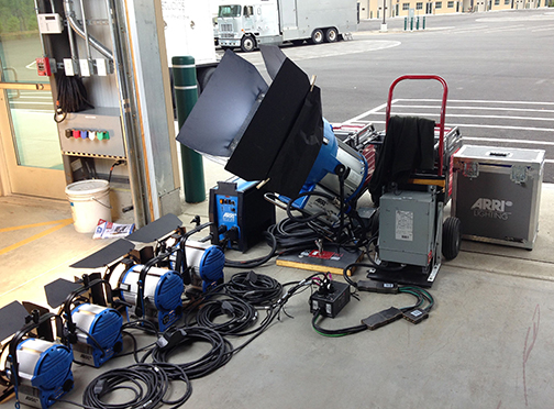
As demonstrated here, our new HD Plug-n-Play Paralleling System can power
a 6K HMI as well as 6000W of additional lights
Another reason one must equalize the load in order to maximize the output of paralleling generators is that, as they generate more cross current, the generators create more 3rd harmonic current (100% more in the example above.) As we saw, this no-load 3rd harmonic is additive with the 3rd harmonic drawn by non-linear loads, and because it is at a higher frequency (180Hz), it contributes exponentially to the generation of heat (400% more.) Since generator loading is limited by allowable temperature rise, harmonic currents act as de-rating factors. In de-rating, the magnitude of harmonic currents is of obvious importance, because as discussed above heat losses are proportional to the square of the current times the square of the harmonic number. In short, an increase in the 3rd harmonic causes increased inverter heat losses, as well as increased copper heat loss in conductors from skin effect.

A peek under the hood of our Paralleling Control Box
Since, as we have seen, all that is required for the generators to pick up equal load is that they start at the same voltage,
our paralleling control box requires some means of adjusting the voltage of one machine relative to the other. Once the generators are tuned
to the same voltage, the Pulse Width Modulation (PWM) control logic of the generator's inverters (a.k.a. Droop Governing) assures that the
same voltage is maintained at each generator output bus as load is applied to the common load bus of the paralleling control box. Since,
the Honda EU generators do not have voltage control knobs like conventional generators (droop governing systems do not permit external
voltage adjustment as isochronous control systems do), voltage regulation must take place in the paralleling box before the common load bus.
Another consideration in paralleling generators is whether the loads will be intermittent or continuous (lasting more than 3hrs.) Which is the
case will determine whether an 80% or a 100% rated breaker is used for over current protection for the combined output bus. Since these terms
“100%-rated” and “80%-rated” circuit breakers are commonly misunderstood, let’s take a moment to review the differences between the two.
Understanding the difference between the two begins with a reading of the 2011 National Electric Code. Section 210.20(A) of the code basically
says that a circuit breaker must be rated such that it can handle the non-continuous load plus 125% of the continuous load. (A continuous load
is one where the maximum current is expected to continue for 3 hours or more.) In other words, the breaker needs an extra 25% capacity of the
continuous load for headroom. There is, however, an exception. When the circuit breaker is listed for operation at 100% of its’ rating, the
additional 25% requirement goes away. Instead, the device simply has to be able to handle the sum of the continuous load and the non-continuous
load.
For this reason circuit breakers are rated for either 80% or 100% of their rating on a continuous basis. According to NEC sizing rules contained
in Section 210.20(A), standard breakers are to carry only 80% of their rated load on a continuous basis. 100%-rated circuit breakers are
permitted to be loaded continuously at their full rating as long as the assembly can handle the additional heat generated and the conductors
are properly connected. Since motion picture lighting set-ups typically burn for hours, and sometimes even for 10-12 hrs. days, day after day,
it is critical that a 100% rated breaker be used in a housing that mitigates the additional heat generated by the additional current. Which
makes the Reliance paralleling control box offered by Honda and pictured below unsuitable for motion picture lighting applications.

The Reliance Controls paralleling box for Honda EU7000 generators
The Reliance paralleling control box uses an 80% GE THQL 50A circuit breaker that will carry only 40 of its 50A rating (50A x .8 = 40A) on a
continuous basis without tripping. It can handle loads up to 50A as long as they are intermittent, but since lighting loads, unlike those of
compressors and tools, are continuous it will trip under lighting loads that exceed 40A. For instance, the breaker on the Reliance paralleling
box would not be able to power a 5kw Incandescent light with its’ 42A load for very long before it would trip.
A second shortcoming to the Reliance paralleling control box is that it offers no means of balancing the load over the two generators,
which means that one generator will reach it maximum load while the other still has unused capacity. The combined effect of an 80% rated
breaker and an inability to balance loads, severely limits the amount of current that can be drawn from the two generators on a continuous
basis. In the case mentioned above of two generators picking up the load in a 3-to-1 ratio, no more than 60A can be drawn between the two
generators on a continuous basis (45A on the generator under full load and only 15A on the generator that is partially loaded.) By
comparison, with modification two generators carrying a balanced load through a paralleling box with a 100% rated breaker can supply
120A of power on a continuous basis.
Cutting-Off Load 3rd Harmonic Currents

Our Transformer/Distros isolate triplen harmonics from the generators so that they can not elevate cross current to a hazardous level.
The final requirement to paralleling two Honda EU6500s or EU7000s inverter generators is to isolate them from the source of load generated harmonics.
Because cross current circulates continuously between generators operating in parallel, the generation of heat by load current
harmonics is a major consideration when paralleling two machines. One way to avoid the problems associated with even low-level harmonic currents
continuously circulating on the neutral is to simply break the link between harmonic generating 120V loads (that require a neutral) and the neutrals
of the paralleled generators. This can be accomplished by using a 240V-to-120V step-down transformer to supply 120V loads. Since transformers are,
in the parlance of the NEC, a “separately derived” system (meaning they are a new source of power) there is no direct electrical connection between
the transformer’s primary and secondary windings, which means that the electrical distribution downstream of the secondary is completely independent
of the generator system upstream of the primary. As illustrated below the only conductor that connects these two systems is the equipment-grounding
conductor.
By removing the neutral connection between the harmonic generating 120V loads downstream of the transformer’s secondary and the generators upstream
of the transformer’s primary, we remove the path on which, not only the most disruptive current (the 3rd harmonic) can flow in a paralleling set up,
but also higher order harmonic currents as well. In other words, a step-down transformer will both create the required neutral connection for
smaller 120V loads, but at the same time isolate the
generators from the 3rd harmonics created by these loads that would otherwise lead to elevated cross current, hot conductors, and overheated
inverters. The harmonic currents generated by small HMIs, Kinos, & LEDs will cause heating of the primary of the transformer (we would have
to use a K-rated transformer for this reason), but the disruptive effect of their flow in the system neutral of the paralleled generators is
eliminated so the generator inverters remain cool.

Powering the same non-PFC 1200W HMI by means of a Transformer/Distro instead
virtually eliminates the 3rd Harmonic
current circulating between the two generators.
If instead of the Splitter Box, we use a transformer to power the 1.2kw HMI in our example above, we can demonstrate the benefit to
be gained by removing the path on which disruptive 3rd harmonic current flows back to paralleling generators. As can be seen in the power quality
meter reading above, the result is that the 3rd harmonic content of the cross current is substantially reduced (by a factor of 150x), which means
the generator’s inverters will operate a lot cooler and not melt down. By eliminating a neutral connection between the gen-set bus and the loads,
a transformer eliminates the reason (overheating by harmonic currents) that prevented the successful parallel operation of Honda EU6500s and EU7000s
for 120V loads - making it now possible to operate more lights, or larger lights, on portable Hondas than has ever been possible.

Parallel operation of two Honda EU6500 generators made possible by our 100A Paralleling Control Box.
To provide power from our 100A Paralleling Box that is readily accessible using industry standard connectors, we would first outfit it
with a "Hollywood Style" 240V Twist-lock receptacle to supply power to the step-down transformer. We would then add a 240V Bates pocket so that we could also
operate larger HMIs (6kw - 9kw) directly off the combined 240V output of the paralleled generators. Depending on which is more convenient, the Bates pocket can be either
hardwired into the box (as pictured above) or on one side of a Hollywood Style Twist-lock Siamese (pictured below) used at the end of the
240V Twist-lock cable run to the step-down transformer.

Hollywood Style Twist-lock Siamese
Which you choose depends on where in relation to the generator you are most likely to use a large HMI. The transformer can then be
used on the other side of the Twist-lock Siamese to create a 120V circuit with a neutral conductor to power small lights. If we take this approach,
240V loads (HMIs larger than 4kw) operate on one “separately derived” power system (i.e. the generators), while 120V loads operate on a second
completely independent “separately derived” power system (i.e the secondary of the Transformer/Distro.)

Our Paralleling Control Boxes syncs the frequency and equalizes the load between the generators.
Besides making it possible to operate two EU6500s or EU7000s in parallel in the first place, the use of a step-down transformer offers many of the same
benefits in parallel operation with two generators as it does with one. Of particular benefit in parallel operation is Line Loss compensation.
Since there are now two generators, as opposed to one, you will need to move them further off set, and run more feeder cable, to avoid picking
them up on audio track. While Voltage Drop from line loss (as opposed to generator droop) is not much of an issue with large single-phase lighting loads (lg. HMIs will operate reliably
from 195-250V), it can be an issue with smaller 120V loads for the reasons discussed above. For this reason, in paralleling set-ups it can be
beneficial to use the voltage adjustment taps of a step-down transformer to compensate for Line Loss by slightly boosting the voltage output
on their secondary side. A slight voltage boost will enable you to place the generators further from set where you won't hear them (an important
benefit since there are now two generators), yet assure that the supply voltage on set does not drop too low.
Without a doubt, our Transformer/Distros makes it possible to operate larger lights, or more smaller lights, on the super quiet Honda EU6500s
and EU7000s than has ever been possible before by isolating hazardous harmonic currents away from the generators. By comparison, the neutral
conductor of a splitter box will return triplen harmonics to the paralleled generators where they will circulate continuously - eventually overheating the
generator inverters.
Transformer/Distros on Wall Outlets
A Transformer/Distro offers the same benefits when used on dryer and range outlets on location. That is, you can also access more power on location, by using a
Transformer/Distro to step down the 240V power available from these common 240V household receptacles to a large 120V circuit capable of powering larger
lights or more smaller lights than you could otherwise. Like it does with either the new Honda EB10000 or our modified Honda EU6500is, our Full Power Transformer/Distros can
convert the 240 Volts supplied by industrial and household receptacles back to 120 Volts in a single circuit that is the sum of the two single phase legs, while effectively managing
the adverse effects of harmonics.

Master shot of an iRobot commercial lit with a 4kw HMI Par (outside) & 1.8kw HMI Par (inside)
powered from a 30A/240V dryer outlet through a step-down transformer/distro.
Note: Sunny feel created by 4k Par on an overcast day.
In fact, a step-down transformer is the only means of using a single phase 3-wire 240V circuit to power 120V lights that meets with the National Electrical Code (NEC). While some gaffers advocate the use of Splitter Boxes to
split 3-wire 240V circuits into two separate 120V circuits, these boxes do not meet the requirements of the NEC when the 240V receptacle is a 3-wire system (H,H,G, & no N.) That is because three wire systems require the
bonding of the Ground and Neutral in the Splitter Box which is in direct violation of NEC [250-23(a), 250-24(a)(5)] according to Mike Holt, of Mike Holt Enterprises, Inc. (A Leading Electrician Training Program in FL).
To quote from the Mike Holt Enterprises website: "The National Electrical Code requires a Neutral-to-Ground connection to be made at service equipment only and there shall not be any Neutral-to-Ground connection on the load
side of service equipment [250-23(a), 250-24(a)(5)]" (full excerpt is
available online.)

Left: Transformer/Distro plugged into a 30A/240V dryer outlet. Right: 4K HMI Par under rain protection powered by Transformer/Distro
The NEC does however permit bonding of the Ground and Neutral on the secondary side of a step-down transformer. That is because, as we learned above, a transformer splits the load of the lights evenly over the two legs of the
single phase circuit, drawing a perfectly balanced load just like the heating elements in the dryer or range for which the circuit was designed. Not only is it permitted by the NEC, it also has the distinct advantage over
a Splitter Box of being able to run larger 120V loads like 5ks, or 2.5 & 4k HMIs with older 120V ballasts.

Left: Arri AS18 1800W Par powered from Transformer/Distro. Right: 4Kw and 1800W HMI ballasts powered from Transformer/Distro.
Our Full Power Transformer/Distros not only enable you to run larger 120V loads off single phase 240V circuits, but it also enables you to more fully utilize the capacity of the 240V circuit by enabling you to load it more
fully. The 20A branch circuits of a Splitter Box don't allow you to fully utilize the power available in a 50- or 30A/240V circuit because the load of a light has to go on one leg of the single phase circuit or the other.
For example, when plugging lights into a Splitter Box, you reach a point where you can't power an additional 1kw light because there is not 8.4 amps available on either one of the box's legs. With a Transformer/Dstro you will
likely be able to add that 1kw light because it splits the load of the light evenly over the two legs (4.2A/leg) of the 240V circuit.
Just like it does with a generator, our Full Power Transformer/Distros also greatly simplify balancing your load on the 240V circuit. Plugging in through a Transformer/Distro you don't have to carefully balance the load over
the receptacles' two 120V legs as you would with a Splitter Box because the transformer does it for you automatically. Now that you are able to fully load a 240V circuit
in a perfectly safe balanced fashion with our Full Power Transformer/Distros, you are able to not only power larger lights off of "house power", but also more smaller lights - thus eliminating the need for expensive
tow generators or dangerous tie-ins.
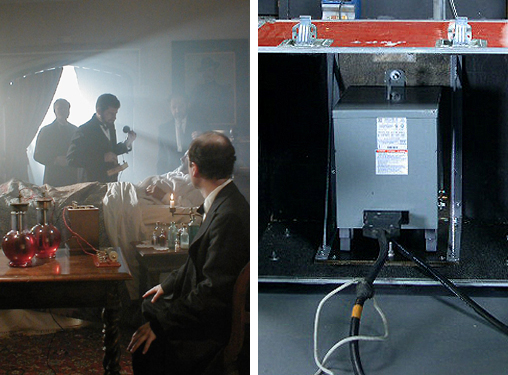
Power for the "Unsolved History" Episode “Presidential Assassins”
filmed at the Ames Estate was drawn from a 50A/240V outlet
through a step-down transformer/distro
Transformer/Distros are particularly helpful in situations where a tie-in is not an option and the budget doesn’t permit for a tow generator. Where the production budget is particularly tight, I use a package consisting of
two Transformer/Distros and one of our modified Honda EU6500is generators. I use one Transformer/Distro to access more power through a 240V circuit on location to run lights inside; while the other I use to bring larger
HMIs in the windows from outside. This approach eliminates the need for a dangerous tie-in or expensive tow generators, it also greatly reduces the amount of cable that has to be run. Over the years, I have used this
combination on many historical documentaries I have gaffed.

For example, I have used this same package repeatedly at a historical mansion in Easton MA called the Ames Estate. A popular state fee free location, the Ames Estate, like many historical house/museums, does not permit tie-ins and the electrical wiring in the house is so antiquated that it is unusable. Fortunately, they have a 50A/240 Volt circuit in the carriage house for a welder they use to repair the mowers they use at the park.

The Ames Estate doubled as a summer house in wealthy Oyster Bay, Long Island
where a mysterious typhoid fever outbreak occurred in August 1906.
For PBS’ American Experience biography of Typhoid Mary, “The Most Dangerous Women in America”, we ran 250V extension cable from the welding receptacle in the carriage house to a 60A Full Power Transformer/Distro placed in the entry hall of the house. Using a 60A Siamese at the Transformer/Distro, we then run 60A 6/3 Bates extensions, down to the library, to the second floor, and back to the maid's pantry. At the end of each run we put another 60A Siamese. A 60A Woodhead on one side of the Siamese gives us 20A branch circuits. The other side we leave open for a large HMI or Tungsten Light. Now we can safely plug 1200 & 2500W HMIs, or even a 5k Quartz, into our own distribution anywhere in the house.

Typhoid Mary in quarantine on an island in New York's East River. Note the view out the window of the East River shoreline at the turn of the century
To maintain continuity between shots on these dramatic historical recreations, we usually bring a 4kw HMI Par in the windows on one side of the room as a sun source and a 1200 par through a window on the other side as a northern light source. We usually power both heads off of a Honda EU6500is through a second 60A Full Power Transformer/Distro. Since the Honda EU6500is can be placed right on the lawn, we are saved from running hundreds of feet of feeder cable back to a tow generator in the drive.

The exterior of the actual location used for the quarantine island. A 30' blowup of a picture of the East River at the turn of the century was rigged outside the windows.
We have been able to use this same basic distribution package at numerous museums and historical houses throughout New England including Sturbridge Village. Fortunately for us, to make ends meet, many historical houses rent themselves out for events and weddings. For that reason, they usually have at least one updated service with 30 or 50 Amp 240 volt circuits for the warming ovens of caterers.
Build a Gen-set System Incrementally
60A Transformer/Distro w/ accessory 20A Break-Out Box (right)
84A Transformer/Distro w/ accessory 20A Break-Out Box (center)
Standard 60A Tranformer/Distro w/Bates Only (left)
What's great about the approach to set power described above is that you can build-up your power generation capacity in an
incremental fashion as your productions require. In fact, you don't even need a generator to increase your production
values. A Transformer/Distro alone can create larger 120V circuits (60A, 84A, or 100A) capable of powering larger HMIs & Tungsten lights, from common
household 240V receptacles (use this link for more details.)
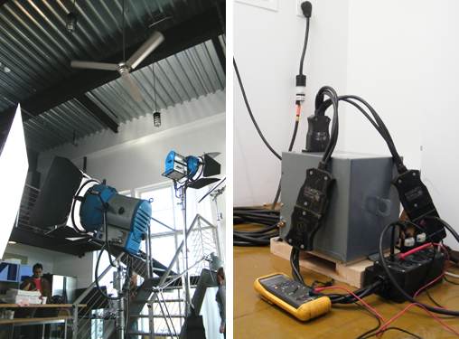
4k & 1.2ks HMI Pars powered from 30A/240V dryer outlet through step-down transformer/distro for Bose still shoot.
All you need is a Transformer/Distro, an adapter to Twist-lock cable and at least one 50'
250V Twist-lock extension cable. If you don't have, or can't rent, Bates style distribution cables and break-out boxes, a 3x20A Edison Break Out Box
wired into the base of the Transformer/Distro will enable you to power more smaller lights off of house power than you could otherwise.

Life style images for Bose print campaign lit by 4k & 1.2ks HMI Pars pictured above.
When house power is not available, a Transformer/Distro will provide access to the full power available from
a 4500-10000W rental generator by stepping-down it's 240V output to a single large 120V circuit (the size of the circuit depends on
the size of the generator.) When you need the most power that can be obtained from a single generator, and it makes sense to invest
in one, the same Transformer/Distro will provide a 60A/120V circuit, capable of powering HMIs up to 4kw and Tungsten lights up to
5kw, from the enhanced 7500W output of a modified Honda EU7000is generator.

A sunny feel is created on an overcast day by a Honda EU6500is powering a 4kw HMI Par and a
1800W ArriMax for a commercial.
When you need a larger daylight source to balance the sun on day exteriors, or to replace the sun on day
interiors, a Paralleling Control Box will combine the output of two modified Honda EU7000s to generate an unprecedented 120 Amps of
power (100A from unmodified EU7000s)(use this link
for more details.)

A sunny feel is created on an overcast day by a Honda EU6500is powering a 4kw HMI Par and a 1800W
ArriMax for a commercial.
A complete paralleling system consists of two modified Honda EU7000s, a Paralleling Control Box, and a Transformer/Distros (either 60-, 84-, or 100 Amps.) The equipment used in each approach described above can be used in a paralleling system.
All you need to start generating 120 Amps on set, is another modified Honda EU7000s and the Paralleling Control Box. What's great about this approach
to set power is that you can build a power distribution/generation system incrementally as your productions grow and then deploy components of the system as
required by your production needs and locations.
(Our new HD Plug-n-Play Paralleling System can power
the new 9kw Arri M90 HMI as
well as 2000W of additional lights)
__________________________________________________________________
The HD Plug & Play Lighting Package
Now that, for the first time ever, it is possible to get 120A from portable gas generatora, the question is how best to use it.
Based upon what we have learned thus far, I have put together a lighting package that I feel maximizes the production capability that can be
obtained from the enhanced 7500W output of a modified Honda EU6500is or EU7000is. I call it the HD Plug & Play Package (HD P&P Pkg.)
(Our new HD Plug-n-Play Paralleling System can power
the new 9kw Arri M90 HMI as well as 2000W of additional lights)
For my HD P&P Pkg. I have picked lights that offer both the greatest production capability as well as the highest output (lumens/watt.) The lights in this package feature new brighter and more efficient "short arc" HMI bulb designs; as well as
new more efficient and compact HMI, Quartz, and now Fluorescent par light designs. And to take advantage of the new math of low line noise, all the lights in my HD P&P Pkg. are Power Factor Corrected. The substantial reduction in line noise that results from using only PFC ballasts on the nearly pure power waveform of our modified Honda EU6500is inverter generator means that we can load the generator to capacity and thereby power more lights than has ever been possible before on a portable generator. Combined with our 60A Full Power Transformer/Distro, these technological advances in lighting design enable the use of bigger lights, or more smaller lights, off our modified Honda EU6500is Inverter Generator, as well as off of common wall outlets.
With the exception of Mole’s new incredibly efficient 5kw Quartz Par light, there are no incandescent lights in my pkg. The reason for this is that, even though incandescent lights generate no harmonic noise, they are also the least efficient light source of the four types discussed. Since eighty percent of the energy consumed by an incandescent light goes into the generation of heat, they generate less lumens per watt of any other light source. Add to that, the fact that the Full CTB gel required to convert incandescent lights to daylight has a transmission factor around .3 (it takes a 1000 Watt incandescent source to generate 300 Watts of day light balanced light) makes them the most impractical daylight source from an efficiency standpoint to operate on a portable generator. For this reason, in my HD P&P Pkg.
I have replaced the traditional role served by incandescent lights - Key and Backlights - with the new Kino Flo Parabeam fluorescent par lights.
Here are a few of the reasons why I prefer the Kino Flo Parabeams, over other fluorescent fixtures, and even LED Panels, as Key and Backlight sources.
__________________________________________________________________


Parabeam Par Lights
The quality of a Key source is more critical in HD production. In High Def every detail of “on-camera” talent is rendered clearly on the screen – even the imperfections. Where LED and traditional
incandescent light sources can exaggerate textural details, fluorescent soft light is more forgiving. Fluorescent movie lights in general make for a better Key source in HD Digital Cinema because
they subdue those same textures and render a more cosmetic appearance. And, since they put out a more continuous spectrum than LEDs, Kino Flos are able to render flesh tones more
accurately (use this link for details.)
The drawback to fluorescents as a key source is that, even though they provide a beautiful soft light and spectrum that renders skin tones well, the light falls off very rapidly and is hard to control. Because their light output drops off rapidly, to serve as a Key source the units need to be positioned close
to the subject they are lighting. These characteristics make them well suited to serve as Key sources in documentary interview set ups where the Keys are typically positioned
close to the interview subject. In that capacity conventional fluorescent lights and LED light panels (with heavy diffusion) can generate a wonderful soft light that wraps
around the interview subject without wilting them. However, in dramatic set lighting, where Key sources must be capable of throwing a distance, conventional fluorescent lights
and LED light panels have only limited applications as fill sources. The broad soft light they put out drops off too rapidly, and is too difficult to control, for them to be
effective as a Key or Backlight source in dramatic set lighting.
What distinguishes the Parabeam fixtures from other fluorescent lights and LED panels is their throw, power efficiency, and the innovative accessories Kino Flo makes available
to control their light output. Accessories include barndoors, a gel frame, a diffusion panel, and Honeycomb Louvers. These features enhance the production capabilities of the
Parabeam fixtures and make them suitable to serve as a key or backlight source where conventional fluorescent movie light fixtures and LED panels are not.
PHOTO COURTESY OF KINO FLO

What makes the Kino Flo ParaBeam fixtures capable of throwing soft light a distance is that they use CAD (computer aided designed) parabolic reflectors to focus the lamp output at about 16 feet (5 meters). This feature makes them well suited to serve as key light sources because it more than doubles the light output of the lamps where it is needed most for lighting dramatic scenes - at a medium distance.
PHOTOMETRIC TABLE COURTESY OF KINO FLO
If you compare the photometric tables of the Parabeam 400 and the Diva 400, you will notice that at 16’ the Parabeam 400 puts out almost three times the light level (28FC) than the Diva 400 (10FC) even though they both use the same tubes. In fact a Parabeam 400 generates as much light at 16’ as the 4’ 8-Tube Kino Flathead 80 fixture, yet uses less than a quarter of the power (2 Amps verses 9.2 Amps.) While the seven amp difference is not a major consideration when using house power, it can make a difference when your power is limited (coming from a portable generator) because you can use four Parabeam 400s for the same power as a 4’ – 8 Bank Kino Flathead 80.

PHOTOMETRIC TABLE COURTESY OF KINO FLO
Kino Flo Parabeam ballasts also include Power Factor Correction circuitry to reduce the return of harmonic currents into the power stream, re-align voltage and current, and improve their power factor to better than .9. Given their efficiency (the 400 draws only 2 Amps, the 200 only 1 Amp) and low harmonics, a number of Kino Flo ParaBeams can be stacked on a portable gas generator without trouble. This makes them an especially efficient light source for use on small portable generators and comparable to the power efficiency of LED light panels. For instance a Parabeam 400 puts out more light than even Zylight’s new high output LED light panel yet draws just .2 Amps more power.
Not only are the Parabeam fixtures more efficient, but they are also more easily controlled – an essential requirement in a Key source.
To control the spread of their light output, Kino Flo makes Honeycomb Louvers in 90, 60 and 45 degree angles. Swapping louvers provides beam control similar to that of swapping lenses on an HMI Par.
   
Barndoors (left), Diffusion Panel (center left), Honecomb Louvers (center right), & Gel Frame (right)
In the open face mode (no louver) the fixture has a wide spread with a hot center beam of light (see light distributions below). The light above and below the beam tapers off in intensity. Although the fixture is square, the beam of light, because of the parabolic reflector, is a broad lateral oval - like that of a wide lens on an HMI Par. The 90° Honeycomb Louver concentrates the light and behaves much like a medium lens on a HMI Par. The beam is slightly oval with a hot center. The light tapers off to a nice soft edge. The 60° Honeycomb Louver further concentrates the light into a smaller, tighter soft edged circle - similar to putting a spot lens on an HMI Par. The 45° Honeycomb Louver is the most concentrated circle of light. It would be similar to putting a narrow spot lens on an HMI Par. The spot displays a beautiful soft edge. In this fashion, the Parabeam’s innovative Honeycomb Louvers offer unprecedented light control for a fluorescent light fixture.
ParaBeam light distribution patterns
PHOTOS COURTESY OF KINO FLO
   
Open face (left), with 90 degree Louver (center left), 60 degree Louver (center right), & 45 degree Louver (right)
Such beam control makes the Kino Flo Parabeams suitable to serve as a key or backlight source where conventional fluorescent movie lights and LED light panels will spill all over the set. These features make the Parabeam fixtures the best candidate of all fluorescent lights to replace incandescent lights in their roll as dramatic key sources. And, the power you save by not using tungsten instruments for Keys and Backlights, enables you to power more lights on the generator than you could otherwise.
__________________________________________________________________

The PFC Tegra 400
The new Kino Flo Tegra 400 combines the best of the old and the new. Like the popular Kino Flo 4’ – 4 Bank fixtures that use Kino Flo’s 4’ T12 True Match tubes, the Tegra 400s are an ideal soft-light
source for location filming. Smaller source fluorescents, such as the compact Diva-Lites, may be slightly brighter, but they are a "harder" source that create denser shadows. The Tegra 400 fixtures, on the
other hand, approximate the quality of soft light from a bounced source without taking up the limited space on set because of their narrow profile.
To compensate for the lower light level associated with T-12 tubes, Kino Flo overdrives each one with a newly designed integrated Power Factor Corrected (PFC of .9) high output ballast. Setting the tubes
in a polished aluminum reflector focuses their light output, giving the Tegra 400 nearly the same output as the popular Diva lights, but with a much softer quality.
Like the Diva 401, the Tegra 400 features on-board dimming capability as well as individual lamp switching.

By incorporating PFC circuitry, the new Tegra ballast uses power more efficiently, minimizes return current, and generates virtually no line noise – making it possible to operate more of them on a portable generator. In fact, the 1.8 Amps that you save by using a Tegra 400 (2.8A) over a traditional 4’ – 4 Bank (4.6A) is almost enough to power two more Parabeam fixtures on a portable generator. Operating at 1/6 the power of comparable tungsten softlights, you can safely plug a Tegra 400 into just about any wall outlet without worrying about what else may be on that circuit already.
Like the original Kino Flo fixtures, the Tegra 400 can take a variety of True Match T12 lamps. They can be used as a daylight source by using Kino Flo KF55 lamps or a tungsten source using Kino Flo KF32 or KF29 lamps. A variety of visual effects for blue and green screen as well as designer colors are available.
  
A variety of Truematch T12 lamps are available
Accessories are available to control or modify the Tegra’s light output. For example, full and half f-stop diffusion Floziers are available to soften the light even more. A Flozier is grid cloth material
that slips over the front of the fixture and provides a large area of white diffusion. The resulting larger area of diffusion further softens the light. This is especially useful when dealing with
reflective subject matters. For example, the harshness of lamp reflections in eye glasses is easily avoided by simply adding a Flozier.

“Bat Wing” Louvers are available to give direction to the light with minimal light loss. While interchangeable 60 and 90 degree honeycomb louvers, similar to those available for the Parabeam fixtures (see above), are available to focus their output much like an HMI par lens does.
Without consuming much power, the Tegra 400 offers abundant shadow-less soft light that can be easily controlled – making it an ideal fill source and an indispensable part of our HD Plug-n-Play lighting package.

60 & 90 Degree Grids control the spread
of the Tegra 400s output
__________________________________________________________________
1800w Baby Max
Without a doubt, the HMI that meets our criterion of generating the most Lumens per Watt would have to be the new Arri 1800w Lens-Less HMI - the “Baby Max.” Featuring the same Academy
Award winning reflector design as the 18000W ARRIMAX, the Baby Max takes advantage of the new 1800w Single Ended Lamp to provide unparalleled performance in a light that can be operated on a 20A circuit.

Comparison between 2.5 Par w/ 20 deg. Med Lens (left), 1800 Baby Max in 20 deg. Spot (Center), and 1800W Par w/ 20 deg. Med Lens (Rght).
The unique ARRIMAX reflector creates diverging parallel rays to produce a crisp light with even distribution through a wide spot/flood range. The result is a lens-less open face fixture with an output greater than that of a
Par, and with the light distribution of a Fresnel. With a spot/flood range of 20 to 60 degrees and a wide usable field angle, the Baby Max is designed to be both versatile and intense.
How bright is the Baby Max? There is a lot of hyperbole flying around regarding the output of the new Arri M18 "Baby Max." Some even claim it has the output of a 4k Par. As a Gaffer, Rental House Owner/Operator, and Arri dealer
I have had the opportunity to work extensively with these heads. While it is difficult to compare a Par, Fresnel, and a Baby Max because they are such different lights, to shed some light on this debate I undertook tests using
a common denominator (the beam diameter to 50% drop off) to compare the photometrics of these heads and here is what I found. Our independent tests confirm that this unique reflector design enables the Arri 1800W Baby-Max to achieve
an output comparable to that of a 2.5kw Par, but with a light quality comparable to a 4k Fresnel. For instance, if you were to spot down the Arri 1800W Baby-Max to the same beam diameter as the 2.5kw Par with Medium Lens in the
photometric table above, it would achieve an output comparable to that of the 2.5k Par. But, as is evident in the picture above and the photometric table below, the light distribution is more similar to that of a 4k Fresnel.

So that the new 1800W lamp can operate on a 20A circuit, Arri has engineered a new Power Factor Corrected 1200/1800 Ballast. Formerly only available in larger ballasts, this advanced electronics reduces current spikes
and harmonics in the power line and contributes to a more economical use of power than typical electronic ballasts. With an Apparent Power of 2250VA, the Arri 1800W Baby Max draws only 19.5 amps at 115V.

With a draw of 19.5 Amps at 115V, the Arri 1800W Baby Max works better on a film distribution system than on location wall receptacles.
The reason, is that many wall outlets are on 15 Amp circuits, and those that are on 20 Amp circuits probably use receptacles only rated for 15 Amps. This is a problem because the Arri 1800W ballast will always trip the common 15amp house circuit and will trip a 20 Amp circuit if there is something else, like a computer or light, on the same circuit. Where you can't always know what else is on the same circuit, or even if it is a 20 or 15 Amp circuit, it is risky to plug the Baby Max into the wall.
Even if you have a dedicated 20A circuit (by unplugging the refrigerator for instance) the draw of the 1800W Baby Max is just too close to the threshold to operate reliably. If there is any line loss from a long cable run, or increased resistance from a hot plug end, the draw of the ballast climbs over 20 Amps and trips the breaker. Because they are only rated for 15 Amps, more often than not the cause of the problem is that a stinger plug-end overheated. The increased resistance that results from the heat causes the voltage to the ballast to drop and so it has to draw even more power to maintain the 1800W load (at 110 Volts it will draw 20.5 Amps.) Which sets up a viscious cycle. The hotter the plug end becomes, the more the voltage drops. The more the voltage drops, the more Amperage the ballast draws. The more Amperage the ballast draws, the hotter the plug end becomes, etc. etc. Unfortunately, the power drawn by the 1800W Baby Max is just too near the operating threshold of a 20A circuit for it to operate reliably plugged into an Edison wall outlet.
The Arri 1800W Baby Max works best on a film distribution system because every Edison outlet is on a 20 Amp circuit, you know what is on the circuit because you are loading it yourself, and because you are distributing the power yourself, you can bring the receptacle to the light. When you can run a 60A whip and drop a Snack Box next to the ballast you won’t have a problem. But, if your style of production requires that you run multiple stingers to plug into a wall outlet, you will likely have problems with plug ends and/or receptacles overheating and tripping breakers.
With the output of a 4k, but using only half the power (19.5A vs 38A), the 1800W Baby Max would be an ideal HMI to operate on a portable generator except that everything that was true of operating them on 20A wall outlets is also true of operating them on the 20A outlets of portable generators. To the problem of line loss and overheating plug ends, you have the added problem that as you add load on portable generators their voltage output drops. It is not uncommon for a generator to drop 10 volts under full load. The 1800W ballast that drew 19.5 Amps at 115 Volts will draw 21.4 Amps at 105 Volts. Again, the power drawn by the 1800W Baby Max is just too near the operating threshold of a 20A circuit for it to operate reliably plugged into a 20A Edison outlet of a portable generator.
The only reliable means of powering a 1800W Baby Max on wall out-lets or on portable gas generators is from a 240V circuit through our 60A Full Power Transformer/Distro. Our Transformer/Distro will convert the 7500W/240V output of our modified Honda EU6500is generator into a single 60A/120V circuit that is more than capable of powering the 19.5A load of a 1800W Baby Max. Outfitted with a 60A Bates receptacle, our 60A Full Power Transformer/Distro can serve as the lynch pin of a distro system that will allow you to move the generator off set (where it won’t be heard), minimize line loss over a long cable run, and provide plug-in pockets conveniently close to the ballasts.
A Distro System consisting of a 60A Full Power Transformer/Distro, 2-60A GPC (Bates) Splitters, 2-60A Woodhead Box
distributes power from a modified Honda EU6500is. Even though the generator is 100' away to reduce noise,
plug-in points remain conveniently close to set).
To record sync sound without picking up any generator noise, all you need to do is add 200' of heavy gauge 250V twist-lock extension cable between the generator and our Transformer/Distro.
This is usually enough cable to place the generator around the corner of a building, or to run it out of a van or truck - which is usually all the additional blimping you need with the Honda EU 6500is.
By using a single heavy-gauge feeder cable in this fashion, you eliminate multiple long stinger runs to the generator and the appreciable voltage drop you would have using standard electrical cords. And,
unlike the 15 Amp U-Ground Edison plugs on stingers, the 30A/250V Twist-Lock plug ends of our high voltage feeder won’t overheat, won’t add resistance, and won’t cause additional voltage drop that will
cause the ballast to draw more power.
Standard 60A GPC (Bates) Splitters and a 60A Woodhead Box.
To assure full line level (120V) on set, our 60A Full Power Transformer/Distro is designed to compensate for the slight line loss you will inevitably have over an extended cable run. If you were to plug it directly into the generator (without feeder cable) and feed the supply side (primary) of the transformer 240 volts, it will give you 127 volts on the load side (secondary ) where you plug in your lights. This slight boost enables you to run 200’ or more of feeder cable to get the generator further from set where you won't hear it, yet assure that the supply voltage on set does not drop below 120V and cause the 1800W ballast to draw more power and trip its’ 20A breaker. And, since our 60A Full Power Transformer/Distro is equipped with a 60A Bates receptacle, you can use standard film distribution equipment like 60A Siameses, 60A Whips, and 60A Snack Boxes to run power to the light (breaking out to 20A Edison pockets next to the ballast), rather than having to run multiple stingers from the ballast back to the generator.
Power-to-Light PFC 800W ballast (left) and PFC 1200W ballast (right) plugged directly into a 60A Woodhead Box.
By providing 60 Amps at full line level through a standard distribution system, our HD Plug & Play Gen-set will reliably operate not just one, but up to three 1800W Baby Maxs on our modified Honda EU6500is generator. And where the 1800W Baby Max has an output comparable to a 4k that is a lot of fire power on a portable generator. Imagine the potential to being able to operate the equivalent of three 4ks off of a portable gas generator.
Our 60A Full Power Transformer/Distro will also enable you to run 1800W Arri Baby Maxs on “house power” from common 240v household outlets as well. Just like it does with a generator, our Transformer/Distro will step down the 240V power of common high voltage household outlets to a single 120V circuit capable of powering multiple 1800W Baby Maxs. Common 240V sources found on interior locations include Range Plugs, Dryer Plugs, and special receptacles installed for Window Air Conditioners. By giving you access to more “house power” through standard distribution equipment, our 60A Full Power Transformer/Distro enables you to reliably operate the 1800W Baby Max without the need for a dangerous tie-in or expensive tow generator. The ability to run multiple 1800W Baby Maxs off of common 240V house receptacles, or the 240V receptacle of portable generators, is one of the best reasons that I can think of to use transformers on set.

So that you can safely plug a Max reflector lens-less HMI into a standard 15A wall outlet, Arri has made the Baby Max backwards compatible with the 1200w SE lamp. With Power Factor Correction engineered into the new Arri 1200/1800 Ballast, the Baby Max with a 1200SE lamp will draw only 11 Amps. The lower draw of
the 1200W SE Lamp will ensure that the Baby-Max will work on any wall outlet. This unique combination of power and luminance efficiency makes the 1200W Baby Max the most powerful HMI that you can safely plug into the wall.
__________________________________________________________________

4/2.5kw HMI Par
As long as there is a sun and moon in the sky there will be a place for a large HMI on interior and exterior sets because small HMIs, Kino-Flos, & LED light panels don’t come close to balancing direct sunlight in day light scenes or covering deep background in night scenes. For powerful daylight fill on exterior sets, to create the feel of hard sunlight on interior sets, or to light deep background on night exterior sets, we recommend a dual wattage HMI Par. I have chosen Arri's 2.5/4kw Par for my HD P&P Pkg. because of its compact design and superior photometrics (see comparison below.)

Not only does the Par configuration of this head provide more output but it is also incredibly versatile. When you need a lot of light for fill on day exteriors you can lamp it with a 4k globe. When you don’t need the punch of a 4k Par,
like on a night exterior, you can swap the 4kw globe for a 2.5kw globe making more power available to run additional lights on a small generator. For example, you save 15 Amps when you swap out a 4k bulb for a 2.5k bulb in a 4/2.5 Par
head powered by a Power Factor Corrected (PFC) electronic ballast. The 15 Amps you save by burning the smaller 2500W globe will power quite a few more lights when you consider that a Kino Flo Parabeam 400 uses only 2 Amps.
To maximize the number of additional lights that you can run off our modified Honda EU6500is generator, we pair the Arri 4/2.5 Par with the Power Factor Corrected (PFC) Power-2-Light 425 LVI Ballast. Power Factor Correction of
this ballast enables the operation of both a larger HMI and more smaller HMIs off of standard wall outlets and portable generators. For example, it is possible to power a lighting package that consists of PFC 1800, & 400
HMI Pars, a couple of Kino Flo ParaBeam 400s, ParaBeam 200s, and Tegra 400s, in addition to the Arri 4/2.5 Par off of our modified Honda EU6500is Generator. Given the light sensitivity of HD Cameras, this is just about all the light you need to light a night exterior.


We chose the Power-2-Light 425 LVI Ballast over others because of its’ greatly simplified design. When the P2L ballast range was designed, the overly complex assemblies of previous designs were avoided, and basic functions were consolidated on easily interchangeable boards, so that servicing could be made as easy as possible. The end result is an “open book” design that greatly simplifies repairs and reduces down time. With the removal of just a few screws the internal components of their ballasts unfold and lay on the service bench like an open book – the power components on the left and the control components on the right. Unlike other manufacturer’s ballasts, components do not need to be removed to gain access to other components.

To make servicing of their ballasts even easier, Power-2-Light ballasts also feature a LED Diagnostic System that enables set technicians, even those with limited technical expertise, to identify and replace defective components in the field. For this reason, the LED Diagnostic System is very straightforward. On the power side they consist of power indicators. There are two on the central PSU card, one for the main internal power supply and another for the isolated Stop/Start safety loop power. On the bridge board there is another for the bridge drive power supply. On the control side the function of the LEDs are labeled. For instance, the current regulator has two LEDs that show regulator and PFC function. The purpose of the LEDs is to indicate basic failures that can be fixed by simply replacing the board. This design approach greatly minimizes down time because, rather than having to send in the ballast for repair, it enables the end user to identify problems and order replacement boards that can be fitted with nothing more than a screwdriver.
__________________________________________________________________

400w ARRILUX HMI
For versatility and high output in a small HMI fixture we recommend the ARRILUX 400w HMI. Its’ par configuration offers punchy directional lighting. Its bug configuration is ideal for soft banks and lantern lights.
And, now an innovative adaptor enables the 400w ARRILUX to be plugged into the back of a Leko to create a controllable high intensity daylight balanced gobo projector.

The ARRILUX Leko adapter is an accessory that offers independent filmmakers production values beyond their limited budgets. In the past, to create the effect of sunlight streaming through windows has required a fairly significant
lighting budget because it required large HMI Fresnels outside windows, powered by large diesel generators. Now, a 400w ARRILUX plugged into a Leko can be used as a powerful daylight gobo projector to throw a window
pattern onto the set creating the effect of sunlight streaming through a window.

The lamp used in the 400W ARRILUX offers many advantages in this particular application. Its "short" arc gap is punctual enough to be very well suited to the optical design of a Leko gobo projector.
The 4 to 1 efficiency ratio of HMI versus Tungsten incandescent creates a gain in light output of two full stops. This huge increase in light level allows patterns to be visible even under the higher ambient light levels of day
light scenes. The 400w ARRILUX plugged into a Leko offers independent filmmakers big budget feature style production values on shoe string budgets.

The 400W ARRILUX antern adapter is an accessory that is especially useful for night exteriors. A 400w HMI Lantern armed out behind talent in a two shot with a 20’ boom arm will create the Reverse Key Lighting that is typically
desired for night exteriors. In this approach, the one light does the job of two Keys and allows for rapid resetting for cross cutting singles because there are not light stands in the background of each single. With this kind of
versatility, the 400w ARRILUX HMI is an HMI light to have if your budget will allow you to have just a few.
To maximize the number of lights that can be operated on our modified Honda EU6500is, we pair the 400w ARRILUX HMI with Arri's Power Factor Corrected (PFC) 200/400
electronic ballast. Drawing only 3.8 Amps (verses the 5.5 Amps required by Joker’s non-PFC 400W electronic ballast), the Arri PFC 200/400 electronic ballast will enable
you to operate an additional Parabeam 400 on a portable generator that you could not otherwise.
__________________________________________________________________

Not officially part of our HD Plug & Play Pkg., the new Mole Richardson 5KW Tungsten Par warrants a mention for those occasions when you want a powerful Tungsten source for night exteriors. Unlike traditional 5KW luminaries, the Tungsten Par uses a specifically designed General Electric 5KW Tungsten Halogen lamp intended for Axial Operation. Like an HMI par, the new Mole 5KW Tungsten Par places the lamp on its side and uses a highly polished parabolic reflector and converter lenses to adjust the field of light. Mole has computer engineered the interaction of lamp, reflector and converter lens to obtain unmatched light performance. This fixture is able to achieve output comparable to a standard 14 inch 10K Fresnel, but is similar in size, weight, and design to the Mole Day Lite 2.5/4k HMI Par.

The new Mole 5KW Tungsten Par puts out as much light as heads twice its size, yet it can to be powered by our modified Honda EU6500is Inverter Generator with our custom 60Amp Full Power Transformer Distro because it draws only 42 Amps (compared to a 10k’s 84 Amps). Or, you can use our 60A Full Power Transformer/Distro to step down the 240V output from wall outlets, thereby eliminating the need for a tie-in or large diesel generator to get the output of a 10k luminary. Without a doubt, whenever powerful 3200K punch or bounce light is required on a set, the Mole 5KW Tungsten Par is the answer.
__________________________________________________________________

At NAB in 2011 Arri introduced the first of their L-Series LED Fresnels: the L7-D, L7-T and L7-C. As is evident in the demo video below of the prototype shown at the
European trade show, IBC 2010, it is clear that Arri has finally engineered a true LED Fresnel.
No longer must you choose between the quality of a true Fresnel light field or the power saving benefits of LED technology. The Arri L7 LED Fresnel combines both:
the cool-burning, energy-efficient advantages of LED illumination with the controllable versatility of traditional Fresnel fixtures (see comparison photos below.)
Shadow Rendering Comparison
 
ARRI L-Series Fresnel/ (left), ARRI ST1 Fresnel (right)
With remarkably clear and defined shadow rendering, excellent field homogeneity, and smooth, continuous flood to spot focus, Arri has taken the best of both worlds and created a truly revolutionary lamp head.
The beam is continuously focusable from spot to flood.
ARRI L-Series Fresnel
  
Light Field in Spot (left), Light Field in Flood (center), Barndoor Cut (right)
And, just like conventional Fresnels, the beam is easily controlled with barndoors and flags - enabling the light to be precisely cut to set pieces and talent (see far right
photos above & below.) Dimming is smooth and continuous, enabling seamless fades to black.
ARRI ST1 Fresnel
  
Light Field in Spot (left), Light Field in Flood (center), Barndoor Cut (right)
With broad spectral output (high CRI), skin tones, costumes and scenery will appear vivid and lifelike; and, the lack of forward heat means that color gels won't burn
through. And, given the discernable amount of light the L-Series Fresnel prototypes throw in the show demonstration video, on what appears to be a 6x6 Ultrabounce rigged
20’ overhead, and under the high ambient light levels of the show hall, seems to suggest that L7 Fresnels have more than enough output to waste some to diffusion and color
gel if one so desires.
__________________________________________________________________

HELIO 270
Light Emitting Plasma
Light Emitting Plasma (LEP) is radically new technology that can produce 144 lumens per watt. In contrast, Tungsten Halogen bulbs produce 15 lumens per watt, LED emitters produce between 65 to 85
lumens per watt (in practical applications), and HMI bulbs produce 90 Lumens per watt. In addition to their intense "flicker-free" output, LEP lamps provide a continuous spectrum that is almost identical to Daylight,
long life, and a ruggedness that outperforms other lamps. These characteristics of LEPs make them an ideal source for motion picture lighting applications. One of the first motion picture lighting instruments
to use this radical new technology, the 270W Helio 270 LEP head offers many practical benefits in producton that HMI and LED luminaries do not (use links below for further details.)
In studio applications, the greatly reduced power consumption of LEPs translates into greatly reduced costs in the build out and operation of studios. Not only is the electrical service required greatly reduced,
money is also saved on the power bill. With higher efficiency, the lamp head draws less power, the fixture produces less heat, and so the studio requires less A/C, which means even less power consumption.
On location, you will be able to generate more light on standard wall circuits and generator circuits than has ever been possible before. Able to operate eight Helio 270W heads on a single 20A circuit, LEP technology
makes it possible to get the output of a 4k HMI from a single wall or generator outlet. When it comes to operating lights on portable gas generators, the greater efficiency of LEP technology is only half the story.
The other half is the fact that the Helio 270 is Power Factor Corrected (PFC.) The power supply used in the Helio 270 has a Power Factor of .99, making it a near linear load. As a result, the Helio 270 uses power
more efficiently, minimizes return current, and generates virtually no line noise.
Where, it is as much the Harmonic Noise that non-PFC HMI, Fluorescent, and LED power supplies (ballasts)
kick back into the power stream, as it is their higher Apparent Power, that limits the total number of them that can be reliably operated on conventional generators; the efficiency and near unity Power Factor
of the Helio 270 means that you can operate more of them on portable gas generators (use this link for details.) For instance, you can operate only four 575W HMIs on a 6500W portable AVR generator, where you can operate 23 Helio 270s (each
with an output comparable to a 575W HMI). And, if the generator is one of our modified Honda EU6500is Inverter generators, you will be able to operate up to 27 Helio 270s on its enhanced 7500W output. I think
you would have to agree, that is a major increase in production capability.
Without a doubt, LEP heads like the Helio 270 take what can be done with a portable generator to a new level. For instance, even when you require a bigger gun like a 4k HMI Par, to say light the deep background
of a night exterior, the low line noise and power consumption of the Helio 270 makes it feasible to operate an entire location package from a single Honda EU6500is. For example, you can operate up to 11 Helio
270s in addition to our PFC Arri 4k HMI Par on the enhanced 7500W power output of our modified Honda EU6500is.
What can be accomplished with a portable gas generator will be even greater when latter this year ARRI introduces to the 4k power class their ARRIMAX reflector technology - creating a 4k head with the light output
of a 12k Fresnel that draws only 37 Amps. Just, think of what can be accomplished with the equivalent of a 12k Fresnel and eleven 575 HMIs with camera systems like the Red Epic or Arri Alexa that are capable of a
fourteen stop exposure range and ASA sensitivities of 1600 without grain – you won’t need anything more than can be operated on the enhanced 7500W output of our modified Honda EU6500is Gen-set. Without a doubt,
the Helio 270 LEP Fresnel used in conjunction with an ARRIMAX 4k will be a real game changer. We look forward to bringing you that combination when it becomes available
With Power Factor Corrected Helio 270 LEP Fresnels, ARRIMAX reflector HMIs, and Kino Flo Parabeams, you won’t need anything more than can be operated on the enhanced 7500W output
of a Honda EU6500is to get decent production values in most production situations – effectively eliminating the need for a large diesel tow generator, with all its hidden
costs. This is what has Harry Box so pumped about our HD Plug & Play Gen-set and why he has included it in the 4th Edition of his “Set Lighting Technician’s Handbook” (use
this link for details.)

"Following the prescriptions contained in this article enables the operation of bigger lights, or more smaller lights, on portable generators than has ever been possible before." - Harry Box, Author "Set Lighting Technician's Handbook"
When you start to use the new math of not only lower power consumption, but also of lower line noise, to calculate what can be operated on a portable gas generator, you
quickly realize, you have what, I would argue, amounts to a paradigm shift in lighting with small portable generators. Where before you could not operate more than a
couple 1200W HMIs on a conventional AVR generator, now you can run a complete lighting package off of a Honda EU6500is Inverter Generator with the aid of a 60A Full
Power Transformer/Distro (use this link for details.)
__________________________________________________________________
Ideal for lighting for DSLRs & the Red Cameras
The fixtures in our HD Plug-n-Play Package are ideal for filming with the CMOS sensors of Digital SLR cameras (like the Canons) and the Red cameras. Since the native color balance of a CMOS Sensor is 5000K,
it looks best when the lighting package consists of 5500K sources. Using tungsten light sources doesn’t make a lot of sense because balancing tungsten to 5500K is not very efficient for the reasons given
above (a 1000W 3200K light becomes a 300W 5500K light when you put Full CTB on it.) Where, it makes more sense to use HMIs to light for CMOS Sensor's native color balance of 5000K because they provide more
lumens/watt and require less filtration with gels, HMIs are expensive to buy or rent.
The Kino Flo Parabeam and Helio 270 Plasma fixtures of our HD Plug-n-Play Package are a cost effective alternatives to HMIs because they are/can be 5500K (with daylight tubes in the Kino) and are an even more
efficient light source than HMIs. The capability of mixing 5500k and 3200k tubes, make the Parabeam fixtures even more efficient. For example, when using the Red’s 5000K color balance, you can warm the lights
without losing output to CTO gel by simply mixing in 3200K tubes with the 5500k tubes.
Compared to LED light panels, the Kino Flo Parabeams offer greater versatility. Able to interchange different color temperature tubes, and vary beam spread with their
interchangeable honeycomb louvers, the Parabeam fixture can do what it takes four different LED fixtures to accomplish – Spot and Flood in both 5500K and 3200K. Not to
mention that you can buy two Parabeam 400 fixtures for what a professional LED light panel costs.
__________________________________________________________________

Extended Run
Auxillary Fuel Tanks
Honda's Eco-Throttle makes the EU6500is incredibly fuel efficient. It will run 4.5 hrs at rated load on a tank of gasoline. So that you never have to interrupt shooting
to refuel, we have developed two accessory Extended Run Auxillary Fuel Tanks. Both tanks require that we install a fuel pump in the generator. But once your generator has been modified with a fuel pump, you
simply set it and forget it. Our Extended Run Auxillary Fuel Tanks offers these other benefits:
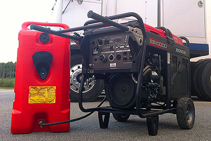
Our 14 Gallon Fuel Caddy enables the Honda EB10000 to run 14 hrs without refueling
 - Allows for safe hazard free operation of the generator for extended periods of time.
- Versatile Hand Truck/Stand or built-in 6 inch wheels enables easy transport of a full tank to set.
- Enables the safe refueling of the generator while running
- Fast set-up with Quick Connect fuel line fittings.
Our 14 Gallon Fuel Caddy (above) has built-in 6 inch wheels. While, our 16 Gallon Auxillary Fuel Tank (below) includes a versatile Hand Truck/Stand. The Hand Truck/Stand not only enables the easy transportation of a full fuel tank
to set, it also enables one-man to easily set up an auxiliary fuel system, and positions the fuel tank at an optimum height.

The 6" wheels built-into our 14 gallon Fuel Caddy enables enables enough fuel
for an entire production day to be transported to set with ease.
Quick Connect fuel line couplers enable fast but safe set up of the fuel tank. A pin and sleeve connection with a
spring-loaded gasket, the Quick Connect couplers engage easily and securely without leaking fuel.

Versatile hand-truck/stand transports 16 gallons of full to set with ease
as well as serves as stand for the Extended Run Fuel Tank
A squeeze bulb enables easy priming of the fuel system. Once the system is primed, the fuel pump will draw fuel from the extended run
tank into the generator. An easily visible large fuel gauge indicates fuel level.

For fast but secure connections our Extended Run Fuel Tanks feature Quick Connect fittings
on the fuel line and generator.
The greatest benefit, however, to our Extended
Run Auxillary Fuel Tanks are that they allow for
safe hazard free operation of the Honda EU 6500is generator for extended periods of
time. By eliminating the need to refuel the generator in the course of a production day, our Extended
Run Fuel Tanks eliminate the extreme fire hazard inherent in
refueling a hot generator.

Our Extended Run Fuel Tanks feature a
Fuel Gauge
and Squeeze Bulb for easy priming of the system.
Countless personal injuries have resulted from fires that have started from fuel spilled on a hot generator while refueling. Our Extended
Run Fuel Tanks eliminate the necessity of refueling the generator; and if you do need to refuel the generator, you can do so at a safe distance by refueling the
Extended Run Fuel Tank rather than the generator fuel tank. Use this link for details on the safety benefits and operation of our Extended Run Fuel Tanks.

Our Extended Run Fuel Tanks enable the safe refueling of the Generator while running.
__________________________________________________________________
Generator Carts and Protective Housings

Protective Cage w/ 10 inch pneumatic casters for Honda EU6500is
Since, portable generators are often used to provide power on locations that are not easily accessible, we have developed several products to facilitate moving them. They range from simple cages on pneumatic tires (pictured
above & below) to fully enclosed generator boxes that can be mounted on any number of vehicles.

Our Honda EU6500is Cage is designed to allow the generator handle to hinge up and down
Our sturdy generator boxes (below) are welded of heavy gauge aluminum diamond plate and are lockable for security. They feature a top lid for easy access for fueling and a hinged end panel for easy loading of the generator
into the box. Doors provide access to all important generator functions. So that the generator can operate within the enclosed box for extended periods without overheating, our generator boxes are equipped with louvers and a
fan to assure proper air-flow. Optional sound attenuation kits are available for further sound dampening.

Our Honda EU6500is Gen Box is designed to allow easy loading of the generator (far left), fan cooling (center left),
easy access to controls (center right), and full
enclosure for protection against rain and further sound attenuation (far right.)
Our generator boxes also offer protection against the elements, further sound attenuation, and a means of securely mounting generators to camera trucks, process trailers, company stake-beds, and grip trailers. We also have a
hitch frame so you can transport them on the back of 1-Ton Grip Vans or SUVs. For ease of mobility around large event sites or movement over rough terrain, we offer several heavy-duty wagon trucks that are tow capable.

Our Honda EU6500is Gen Box can be mounted onto a hitch frame (left), or heavy-duty wagon trucks (far right.)
Our wagon trucks are constructed of heavy 12 gauge reinforced steel decks sized to accommodate both a generator box and our 60A Full Power Transformer/Distro with cable. Full 1 inch diameter axles, large 12 inch
pneumatic tires, and fifth wheel steering assure easy transportation over rough terrain.

Wagon truck options include 4 wheel towable trucks with 12 inch pneumatic casters for Honda EU6500is
pneumatic tires (left), or heavier-duty 8 wheel towable trucks with 16 inch pneumatic casters for Honda EU6500is pneumatic tires (right.)
All wagon
trucks feature fifth wheel steering for greater maneuverability of heavy loads.
Wagon trucks with fifth wheel steering are easier to maneuver over rough terrain with heavier loads because the steering wheels pivot on a center point and so encounter less friction when turning than would be encountered
in a swivel caster. This is especially true when softer, wider pneumatic wheels are required for greater mobility on rough or uneven surfaces.
A Ring Drawbar/T-Handle with a 2-1/2 inch I.D. ring allows you to hitch our wagon trucks to a pin and clevis coupler for low-speed towing with Gators or ATVs (the 3500lb capacity is reduced by 25% when towing.)
The T- handle features two vinyl handgrips to allow two man operation where required. For towing over especially rough or uneven terrain, we offer a wagon truck with eight 16 inch x 4 inch 4 ply pneumatic wheels.
Because, our 8 wheel truck distributes the load of the Tranformer/Distro, cable, and generator over a larger surface area, it offers much greater stability and mobility when towing over rough terrain.
__________________________________________________________________

Portable generators are quite often used to provide power in situations where it is not possible to get a large tow plant. Since, many of these situations also include working in, on, and around
water (to provide power on boats, beaches, and around remote lakes and streams) we have designed our HD Plug & Play Pkg. Gen-set to meet OSHA requirements (most portable generators do not) and
operate safely in wet environments.
To assure safe distribution of power from the generator in the wettest conditions, our 60A Full Power Transformer/Distro uses an Epoxy Encapsulated Core with
a “3R” all weather rated housing. With the transformer windings, core, and lead
connections sealed in epoxy inside a tough, waterproof casing, our 60A Full Power Transformer/Distro will withstand the harshest outdoor conditions - making them the clear choice for power distribution from portable generators on wet locations.

A 100 GFCI with our 60A Transformer/Distro meets OSHA requirements
for use of a Honda EU6500is generator on work sites.
Since, moisture can also cause ground faults that can endanger the lives of those working on wet sets, many municipal electrical codes and OSHA require the use of Ground Fault Circuit Interrupters
(GFCIs) in wet conditions. Even though, ground fault protection can eliminate electrical hazards and save lives, many productions shoot without GFCIs because they are prone to tripping when used
with Kino and HMI ballasts, or are simply not available on the super quiet generators (the Honda EU6500is for instance does not have GFCIs.) They are also not
commonly available for 120V branch circuits larger than 20 Amps. To eliminate the problems associated with the use of common GFCIs on portable genertors, we bond the Neutral to the ground in our 60A Full Power Transformer/Distros
and offer a 100A GFCI specifically designed for use with motion picture lights up to 6kw. When used with our 60A Full Power Transformer/Distro, our 100A GFCI brings the Honda EU6500is generator into full OSHA compliance
(it does not meet OSHA requirements for use on work sties otherwise.)
100A GFCI provides ground fault protection on wet locations
Designed for underwater, outdoor, and wet-location filming, our 100A GFCI provides UL943 Class “A” protection. Featuring a 6mA trip level, our 100A GFCI assures protection for
people and equipment from ground faults. Unlike standard home GFCIs, it uses an "Inverse Time Curve" to prevent nuisance tripping by electronic Kino & HMI ballasts that can cause
costly production delays. And, to deal with the harmonics that non-PFC Kino & HMI ballasts kick back into the power stream (that will cause other GFCIs to trip), our 100A GFCI
includes a harmonic filter with a frequency response up to 120 hz. 3rd harmonics are attenuated by 50%, and by 500 Hz are down to 20%. Attenuated by the filter, the harmonics generated by
dirty loads such as non-PFC Kino & HMI ballasts, pose less of a problem. Finally, to assure your piece of mind, it includes a test function that enables you to confirm it works. Adapted with 60A Bates connectors, it is easy to
install inline after our 60A Full Power Transformer/Distro and will provide safe and secure ground fault interruption for the entire distribution system – meeting and exceeding OSHA requirements for the use of portable generators on work sites.

To protect the generator during the harshest of weather conditions we offer both a rain hood (above) or fully enclosed rain housing (below.)

Honda EU3000 water tight sound insulated genertor box (caster kit available.)
__________________________________________________________________
About the Author

Guy Holt presenting his nationally recognized curriculum on
"Electrical Hazard Protection for the Entertainment Industry" to members of IATSE Local 481.
Guy Holt has served as a Gaffer, Set Electrician, and Generator Operator on numerous features and television productions (for a partial list of credits see his imdb listing).
Guy Holt developed a nationally recognized curriculum on "Electrical Hazard Protection for the Entertainment Industry" that he teaches through the IATSE Local 481 Electrical Department "TECs" Program (pictured above.)

Guy Holt presenting to the Electrical Department of IATSE Local 481 as part of the
“Advanced Power and Generation for Set Lighting
Technicians Seminar”
Guy Holt
presented on Harmonics to the Electrical Department of IATSE Local 481 (pictured above) as part of the “Advanced Power and Generation for Set Lighting
Technicians Seminar” offered by Russ Saunders of Saunders Electric (the provider of power generation services for the Academy Awards since 1952 and a recipient of a technical Emmy). Here is what industry leaders have to say:
Guy Holt is "among the 1% of film technicians world wide that truly understand the dynamics
of power generation and Harmonics." - Russ Saunders, Saunders Electric
Guy Holt demonstrates a "broad technical and scientific understanding, and (is) blessed with a nice real world practical point of view ... (he possesses a) mix
of knowledge and the ability to communicate it effectively. " - David Pringle, Chairman and CTO, Luminys Systems Corp, Manufacturers of Softsun and Lightning Strikes lumnaries.
"Great work!... this is the kind of thing I think very few technician's ever get to see, and as a result
many people have absolutely no idea why things stop working." - Harry Box, Author "Set Lighting Technician's Handbook"
"Following the prescriptions contained in this article enables the operation of bigger lights, or more smaller lights, on portable generators than has ever been possible before." - Harry Box, Author "Set Lighting Technician's Handbook"
This article is cited in the 4th Edition of Harry Box's "Set Lighting Technician's Handbook" and featured on the companion website
"Box Book Extras" (click on link below for more details.)
Guy Holt's other credentials include:
- IATSE Local 481 Certified Gaffer
- IATSE Local 481 Certified Generator Operator
- IATSE Local 481 Certified Lighting Balloon Operator
- Certificate Holder of the MQ Power "MQP Special Generator (Crawford) Technical Service Seminar"

Guy Holt participating in a panel discussion as part of IATSE Local 481's Advanced HMI & LED Lighting
Seminar (Fred Horne, Former Arri Northeast Sales Rep pictured left)
Guy Holt is also the owner of ScreenLight & Grip, a lighting and grip rental company in Boston, MA renting Honda, MQ, and Crawford generators for motion picture production
for 18 years. Inquiries can be sent to the attention of Guy Holt at rentals@screenlightandgrip.com

Guy Holt preparing to modify a Honda EU6500is generator
__________________________________________________________________
Each component of our
"HD Plug & Play Package"
is available for
Rental or Sale
Our HD P&P Pkg. capitalizes upon the following technological advances in lighting and production technology by
Mole Richardson, K5600,
Power to Light, Kino Flo, and Honda.
- More efficient and compact HMI, Quartz, and now Fluorescent Par Lights.
- Brighter and more efficient "short arc" HMI bulb designs.
- 120/240V Electronic HMI ballasts with Power Factor Correction.
- Cool burning, energy efficient Fluorescent Lighting Fixtures.
- Innovative new rigging hardware.

These technological advances in lighting design now enable the use of bigger lights, or more smaller lights, off of standard wall outlets or off
a new generation of quieter and more powerfull Honda Inverter Generators. Click here for more detailed information on our HD P&P Pkg.
__________________________________________________________________
Bibliography
Aim Energy. "All You Want To Know About Harmonics." (Online) Available http://www.cpe-aim.ca/html/aimenergy/Harmonics/harmonics.htm
Arrillaga, Jos. Power System Harmonic Analysis. New York: John Wiley & Sons, 1997
Box, Harry. Set Lighting Technician's Handbook, Third Edition. London: Elsevier Press, 2008
Box, Harry. "Electronic Ballasts", FILMCREW Magazine.
Brown, Blain. Motion Picture and Video Lighting, Second Edition London: Elsevier Press, 2008
Caterpillar. "Application and Installation Guide for Electric Power Applications, Engine and Generator Sizing (CAT publication LEBE5294." (Online) Available at the Caterpillar Electronic Media Center.
Croft, Terrell. American Electricians' Handbook, 15th Edition New York: McGraw Hill, 2009
De Armond, John. "The “Hows” and “Whys” of Inverters and Inverter Generators." (Online) Available bellsouthpwp.net/j/o/johngd/files/rv/inverter_generator.pdf, 2000
DeDad, John. "The How's and Why's of Harmonic Distortion." (Online) Available http://ecmweb.com/mag/electric_hows_whys_harmonic, Jun 1, 2006
Diesel Service & Supply. "How Does a Generator Create Electricity? How Generators Work." (Online) Available http://www.dieselserviceandsupply.com/How_Generators_Work.aspx
Dugan, Roger. Electrical Power Systems Quality. New York: McGraw Hill, 2003
Engdahl, Tomi. "Ground loop problems and how to get rid of them." (Online) Available www.blueguitar.org/new/articles/other/ground_loop.pdf,1997-2000
Federal Construction Council. "Effects of Nonlinear Loads on Electrical Circuits and Equipment, Summary of a Symposium." (Online) Available http://books.google.com/
Fehr, R. "Harmonics Made Simple." (Online) Available http://ecmweb.com/powerquality/electric_harmonics_made_simple/
Fuchs, Ewald. Power Quality in Electrical Machines and Power Systems. London: Elsevier Press, 2008
Honda Power Equipment. "EU6500iSA Model Detail." (Online) Available http://www.hondapowerequipment.com/products/modeldetail.aspx?page=modeldetail§ion=P2GG&modelname=EU6500ISA&modelid=EU6500ISA
GILLETTE GENERATORS, "KLEEN-POWER." (Online) Available http://www.gillettegenerators.com/klnpower/kpower01.html
Kaiser, Kenneth. Electromagnetic Compatibility Handbook. Boca Raton: CRC Press LLC, 2005
Kleinschmidt, Kirk. "A Closer Look at Inverter Generators." (Online) Available www.arrl.org/files/qst-binaries/QS0608Kleinschmidt.pdf
Kumar,Suresh. "NON-LINEAR LOADS AND THEIR INTERACTION WITH DIESEL GENERATOR UNITS." (Online) Available http://sureshks.netfirms.com/article/upsgen/upsgen.htm
Lemerande, Cory J. "Harmonic Distortion: Definitions And Countermeasures, Part 2." (Online) Available http://ecmweb.com/mag/electric_harmonic_distortion_definitions_2/, May 1, 1998
Mahon, L. L. J. Diesel Generator Handbook. London: Elsevier Press, 2004
Mehrdad, Mike . "Influence of Voltage and Current Harmonics on Behavior of Electric Devices ." (Online) Available www.mantenimientomundial.com/sites/mmnew/bib/notas/Harmonics.pdf
NDT Resource Center. "Self-Inductance and Inductive Reactance." (Online) Available http://www.ndt-ed.org/EducationResources/CommunityCollege/EddyCurrents/Physics/selfinductance.htm
Pacific Gas and Electric Company, "Power System Harmonics." (Online) Available http://www.pge.com/includes/docs/pdfs/mybusiness/customerservice/energystatus/powerquality/harmonics.pdf.
Power & Systems Innovations, "Harmonic Currents." (Online) Available http://www.lightningconsultant.org/iread/harmonic.htm, 1995
Power Medix. "Harmonics." (Online) Available http://www.powermedix.com/articles/harmonics
Siemens. "Sinusoidal pulse width modulation." (Online) Available http://www.sea.siemens.com
Short, Thomas Allen. Electric Power Distribution Handbook. Boca Raton: CRC Press LLC, 2004
Suburu Robin Power Products. "Inverter - Silent Generators>" (Online) Available http://209.62.29.198/series.aspx?sid=14
WAGGONER, JOHN. "Power Quality and Harmonics.", (Online) Available http://www.sandwcontracting.com/power_quality.htm
__________________________________________________________________

|

Our exclusive Porta-Grid Clamp rigging Kinos and
Arri HMI above and below drop-ceiling.
|
|
Get
your new catalog today!
By Mail:
Contact us at lightsne@aol.com so that we can mail you a new 2002 Catalog.
Down Load: You can download a PDF version of our new
Year 2002 Rental Catalog by clicking on the following link: ScreenLight&Grip Rental 2002.pdf
If you need the Acrobat Reader you can download it for free
at: adobe
acrobat
On-Line:
log onto www.ScreenLightandGrip.com to see an expanded version of our 2002 Catalog with product shots and production stills.
|
__________________________________________________________________
|
CLICK BELOW FOR OUR WEBSITE AND A CHANCE TO WIN!

Phone (781)326-5088 ***
Fax:(781)326-4751
*** lightsne@aol.com
|
| |
