
The HD Plug-n-Play Gen-set System
Operator's Manual
This operation manual is intended as a supplement, and not a replacement for the Honda EU 6500is operation manual. It supersedes the Honda manual in respect to peak and continuous load rating of the generator and will instruct you how to set up the generator for use with the Full Power Transformer/Distro.
UNPACKING/ASSEMBLY INSTRUCTIONS
The Full Power Transformer/Distro is bolted and strapped to the pallet for shipping. You will need to unbolt it and mount it onto the Sled (if
included in your order) as instructed below.
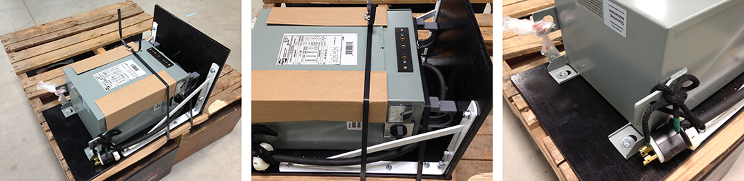
Step 1: Cut the strapping (middle). Step 2: Remove the lag bolts holding the Transformer/Distro to the pallet (right)
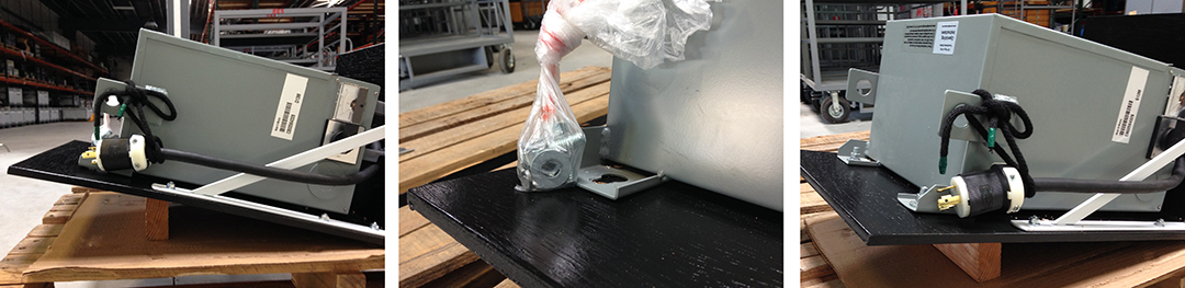
Step 3: Elevate the end of the Sled with blocking (not included)(left). Step 4: Locate carriage bolts tied to Transformer/Distro (middle).
Step 6: Bolt Transformer/Distro to the Sled with carriage bolts (right). Step 7: Tilt upright only after securing Transformer/Distro to Sled.
GENERATOR DESIGN FEATURES
Power Producing Circuits
This generator is equipped with two power-generating circuits. When the voltage selector switch is in the 120V/240V position, each of the two power producing circuits supplies power to specific 20A & 30A receptacles and half of the four pin twist-lock receptacle. When the voltage selector switch is in the 120V ONLY position, the power producing circuits operate in parallel, providing power to the 20A and 30A twist-lock receptacles only.
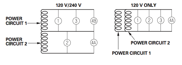
Alternate Circuit Configuration of Honda EU6500is
Eco-Throttle System
The Eco-Throttle system automatically adjusts the engine speed to the load on the generator. When lights are turned on and off, the Eco-Throttle system will adjust engine speed to adjust power output to the electrical load.
System Ground
The Honda EU6500is portable generator has a system ground (not to be confused with the "Grounding Terminal") that connects the generator frame components to the ground terminals in the AC output receptacles. The system ground is not connected to the AC neutral wire. If the generator is tested with a receptacle tester, it will not show the same ground circuit condition as for a home receptacle for this reason.
Grounding Terminal
The generator grounding terminal is connected to the frame of the generator, the metal non-current-carrying parts of the generator, and the ground terminals of each receptacle.
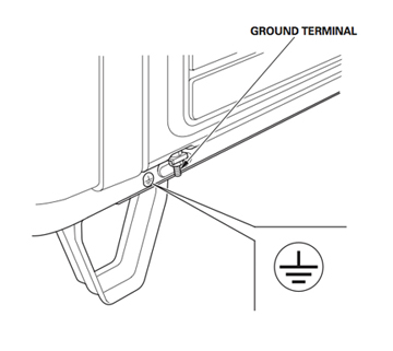
Generator Grounding Lug (there is one similar on the Transformer/Distro)
When connected to the generator, the grounding terminal of the Full Power Transformer/Distro is also connected to the ground terminals of each receptacle (both on the Transformer/Distro and Generator), the frame of the generator, and the metal non-current-carrying parts of the generator (the System Ground.) Note: Ground and Neutral are bonded in the Transformer/Distro and not the generator.
Before using either grounding terminal (on either the Transformer/Distro or Generator), consult a qualified electrician, electrical inspector, or local agency having jurisdiction for local codes or ordinances that apply to the intended use of the generator.
Using GFCI Circuit Protectors
Since, the generator's system ground is not connected to the AC neutral wire, GFCI circuit protectors will not operate reliably when plugged into the generator's power output panel. For reliable operation of GFCI circuit protectors, plug them into the power distribution system downstream of (after) the Transformer/Distro. Use GFCI circuit protectors specifically designed for motion picture lighting applications (like those manufactured by Bender and Shock Block) when using HMI or Fluorescent lighting loads
Use this link for more information on grounding or the use of GFCI circuit protectors .
Special Requirements
There may be Federal or State Occupational Safety and Health Administration (OSHA) regulations, local codes, or ordinances that apply to the intended use of the generator. Please consult a qualified electrician, electrical inspector, or the local agency having jurisdiction.
In some areas, generators are required to have catalytic converters to reduce air born pollutants and/or be registered with local utility companies. If the generator is used at a set construction site, there may be additional regulations that must be observed.
SYSTEM SET UP
Place the Full Power Transformer/Distro on or near your set. Place the generator off set where it will not likely be heard (around the corner of a building or in the back of a truck or van.) Run high voltage three pin twist-lock extension cable between the Transformer/Distro and the generator. Use the three pin female twist-lock to 4 pin male twist-lock adapter cable to plug the Transformer/Distro into the generator.

Gen-Set Set-Up
Given the choice between running more twist-lock extension between the generator and the Transformer/Distro and running more 60A Bates extension between Transformer/Distro and set, always run more twist-lock extension between the generator and the Transformer/Distro so that the Transformer/Distro can compensate for line-loss.
Use this link for more information on line-loss and how to compensate for it.
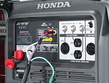
Generator Control Panel
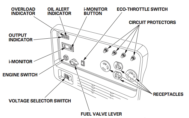
Honda EU6500is Control Panel
Voltage Selector Switch - Generator
The voltage selector switch changes generator output to produce "120V ONLY" or "120/240V." The Full Power Transformer/Distro is connected to the 4- prong receptacle and the switch set in the "120/240V" position.
Important: Select the voltage before starting the engine.

Voltage Selector Switch
Note: with the Switch Position set for "120/240V", the 120V and 120/240V receptacles can be used simultaneously. With the Switch Position set for "120V ONLY", only the 120V receptacles can be used. Using the
Full Power Transformer/Distro connected to the 4- prong 240V receptacle in the "120V ONLY" position could damage electronic ballasts.
Voltage Selector Switch - Transformer/Distro (Optional Upgrade)
The voltage selector switch on the Transformer/Distro selects between three voltage boost settings. Position 1 is OFF. Position 2 is no boost. Position 3 is a 5% boost. Position 4 is a 10% boost. For example,
if you were to plug the Transformer/Distro directly into the generator, without using cable extensions, so that the volage supplied to the Primary (Supply) Side of the Transformer/Distro is
240V, the output voltage on the Secondary (Load) Side of the Transformer/Dstro will be 126V (120V x 1.05 = 126V.) The purpose of voltage
selection on the Transformer/Distro is to compensate for for Voltage Drop as a result of load on the generator and line-loss over a long cable run.

Transformer/Distro Voltage Selector Switch
Voltage Drop on the Generator and Line-Loss on cable is a function
of load - i.e. the greater the load, the greater the voltage drop. For this reason, it is best to start with the Voltage Selector Switch set so that the Voltage Meter on the Transformer/Distro reads 126V (start
a little high - anticipating that it will drop under load.) Turn on all your lights so that the generator is carrying your full load. Now check the line voltage on the Voltage Meter on the Transformer/Distro. If the line
voltage has dropped below 120V, step up the Voltage Selector Switch to the next higher setting until the Voltage Meter on the Transformer/Distro reads 120V or slightly more. Long cable runs will require a higher initial voltage reading on the Transformer/Distro.
Note: Electronic HMI ballasts may shut down from the momentary interruption in power when switching between boost settings. For this reason you may want to turn off HMIs before changing boost settings and allow time for the heads to cool before attempting to restrike them.
True RMS Volt/Amp Meter - Transformer/Distro (Optional Upgrade)
To assist in compensating for voltage drop, the Transformer/Distro can be outfitted with a True RMS Volt/Amp meter. The meter operates as follows:
upon application of AC power to the Bates receptacle, the True RMS meter will first perform a self-test routine and then continuously display AC volts
with the VOLTS LED annunciator illuminated.
The display will remain in the VOLTS mode as long as the front panel "SEL" button is not touched. After the
unit powers up to normal operation in the VOLTS reading mode, momentarily (approximately one second) touching the "SEL" button on the unit's front
panel three times in succession will cycle the display to AMPS, WATTS, and end at POWER FACTOR (PF.) Momentarily touching "SEL" a fourth time will
return the display back to the VOLTS reading mode.
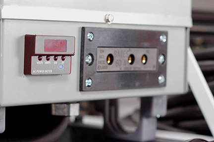
Transformer/Distro True RMS Volt/Amp Meter
Holding the "SEL" button down for 3 seconds will place the unit in a continuous auto-cycling mode,
and the display will repetitively scroll through all four measurements, with each measurement remaining displayed for 3 seconds. When the continuous
auto-cycling mode is initially selected, the unit will briefly display "Auto On" before continuous cycling begins. Momentarily touching the "SEL"
button again will cause the unit to briefly display "Auto OFF" before it returns to the fixed VOLTS reading mode.

Transformer/Distro True RMS Volt/Amp Meter
Any one of the four display modes can be configured to be the default mode so that it is displayed automatically upon future application of AC power to
the Bates receptacle. For example, the unit can be configured to always power up in the AMPS mode if that is desirable. To set the unit to always read
AMPS on power up, tap the SEL switch until the AMPS mode is displayed, and then leave the unit in this mode for at least 60 seconds. As long as the
SEL switch is not pressed again during the 60 second interval, the unit will configure itself to always power up displaying the chosen mode, which is
AMPS in this example.
Balancing Your Load
120V ONLY Position
When the voltage selector switch is in the 120V ONLY position, you do not need to spread the load over the receptacles. You must, however, make sure the load on any receptacle does not exceed its available power.
120V/240V Position
When the voltage selector switch is in the 120V/240V position, and you are using the generator without the Full Power Transformer/Distro, you must balance the load. Divide the load between the two sets of receptacles.
Balancing is necessary because each set of receptacles is powered by only one power producing circuit. When you are using the Full Power Transformer/Distro, you do not have to balance any load that you plug in through the
Transformer/Distro - it balances the load on the two electrical circuits of the generator automatically. Any load plugged directly into the generator power output panel will unbalance the load and reduce the overall load that can be run on the generator. Run loads through the Transformer/Distro whenever possible.
Overload Indicator/Master Breaker
If the generator is overloaded, or if there is a short circuit in a connected load, or if the inverter is overheated, the red overload indicator will go ON. When the generator is operating overloaded, the red overload indicator will stay ON and, after about five seconds an internal electronic master breaker (as opposed to the individual receptacle push button panel fuses) will interrupt current to all of the generator receptacles and the connected load(s) will shut off, and the green output indicator will go OFF.
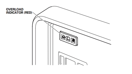
Overload Indicator Light
To re-set the internal master breaker, turn off the loads connected to the generator. Turn off the generator. Reduce the load on the generator (use the load specifications in the table below as guide) or isolate and eliminate the load with a short circuit. Restart the generator.
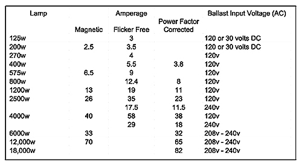
Approxmate Load in Amps of Common HMI Lights
Note : Magnetic HMI ballasts strike at a higher load and then settle down to a constant steady state load. For this reason, the red overload indicator may come on when striking magnetic ballasts. This is permissible if the red overload indicator goes off after about five seconds. If the red overload indicator stays on, shut-off the magnetic ballast. Recalculate your load to assure that at its steady state load, the addition of the magnetic ballast does not overload the generator. If it will not, shut off all other loads on the generator. Re-strike the magnetic ballast, and wait for the light to come up to full brightness before turning back on the loads that were shut off.
Note : Substantial overloading that continuously lights the overload indicator (red) may damage the generator. Marginal overloading that temporarily lights the overload indicator (red) on a regular basis may shorten the service life of the generator. After reaching 7000 Watts on the i-Monitor display, increase your load carefully so that you do not overload the generator.
i-Monitor
The i-Monitor is a user interface that allows the operator to view (when the generator is running) total operating time in hours, generator output, engine RPM, battery voltage, and error messages. The different display modes are selected by pressing the i-Monitor button.
i-Monitor at Startup
During start up, the i-Monitor display and all three indicators will simultaneously blink once. The condition of the i-Monitor display and all three indicators can be checked. Once the generator is running, the Output indicator (green) and the i-Monitor display will remain lit.
i-Monitor Display
The i-Monitor display is divided into two screens. The single-digit screen displays the i-Monitor mode, which is represented by a number 1 through 4 (1 = Operation Hours , 2 = Approximate Power Output, 3 = Engine RPM,
4 = Battery Voltage). The four-digit screen displays the four mode values or any activated error messages.

i-Monitor Display
i-Monitor Display Mode 2 - Power Output
This mode displays an approximate generator output on the display screen. The output is expressed in VA (volt-amperes = Watts). The output value is not an exact measurement and should be regarded as a reference only. Power output will not display until a load is connected to the generator. To avoid overloading the generator, use the i-Monitor Display in Mode 2 to carefully load the generator after reaching 6500 Watts.
Use this link for more detailed information on using the i-Monitor Display
to load the generator.
Eco-Throttle Switch
The Eco-Throttle Switch turns on and off the Eco-Throttle System. With the switch in the ON position, engine speed is automatically lowered when loads are reduced, turned OFF, or disconnected. When loads are turned ON or reconnected, the engine returns to the proper speed to power the electrical load.
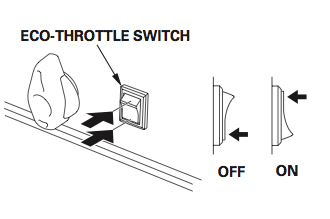
Eco-Throttle Switch
In the OFF position, the Eco-Throttle system does not operate. With the exception of the special cases below, run the generator with the Eco-Throttle system ON to reduce the noise output of the generator.
When to turn the Eco-Throttle system OFF
1) Loads with large start-up power demands (2.5kw & 4kw HMI Magnetic Ballasts) may not allow the engine to reach normal operating rpm when they are connected to the generator. For these loads, turn the Eco-Throttle to the OFF position to strike the light. If the engine still will not reach normal operating speed, turn off another load, restrike the Magnetic Ballast. Once the HMI lamp has come up to full level and the engine has reached normal operating rpm, turn the load that was turned off back on. If the engine becomes sluggish and will not reach normal operating speed, check that the overall load does not exceed the load capacity of the generator.
2) When using a large electrical load like an Incandescent 5k or Par 64 Six Light, turn the Eco-Throttle switch to the OFF position to reduce voltage fluctuation when a large electrical load is turned on.
3) The Eco-Throttle system is not effective for use with loads that require only momentary power - such as, when multiple lights are to be turned on simultaneously for a lighting effect. If the accumulative load will be turned ON and OFF quickly, the Eco-Throttle switch should be in the OFF position.
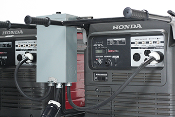
Paralleling Operation
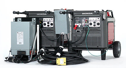
Paralleled Honda EU7000s with 84A Transformer/Distro
The following components are required to parallel two Honda EU 6500s or EU7000s:
two Honda EU generators (either 6500 or 7000), a paralleling control box, 50A Twist-Lock Extension Cables, a Paralleling Siamese, and either a 60-, 84-, or 100 Amp Transformer/Distro.

A complete system consists of (from left-to-right) two Honda EU 6500s or EU7000s:
two Honda EU generators (either 6500 or 7000), a paralleling control box, 50A Twist-Lock Extension Cables, a Paralleling Siamese, and either a 60-, 84-, or 100 Amp Transformer/Distro.
Step 1: System Grounding of Paralleling Set-Ups
The first step in setting up two generators for parallel operation is to establish an Equipment Grounding Conductor (EGC) between the Paralleling
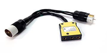
Control Box and the two generators. In the case of two Honda EU6500 generators, all that is required is to plug the 4-pin twist-lock pigtails of
the control box into the 240V 4-pin twist-lock receptacles on the generators - the ground pin of the twist-lock plug establishes a continuous EGC
between the Paralleling Control Box and the generator frames.

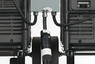
Ground Wire Extension
In the case of two Honda EU7000 generators, grounding wires like that pictured above are used to ground the Paralleling Control Box to the frames of the EU7000 generators.
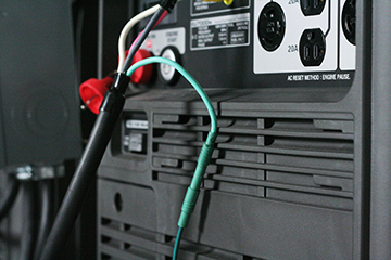
This is accomplished by first plugging the male 4mm plug of the grounding wire into the female 4mm connector of each of the Paralleling Box pigtails.
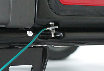
The ring terminal at the other end of the grounding wires are then fastened to the grounding connection point on the generator frame (see photo above for location.)
Step 2: Power Connections
The Paralleling Control Box for Honda EU6500s
The next step in setting up two generators for parallel operation is to make the power connections between the Paralleling Control Box and the two
generators. In the case of two Honda EU6500 generators, all that is required is to plug the 4-pin twist-lock pigtails of the control box into the
240V 4-pin twist-lock receptacles on the generators - the pin configuration of the twist-lock plug assures the power from the two generators are
phased properly.
CAUTION - Risk of Electrical Shock - CAUTION
To avoid electrical shock, connect paralleling box to generators BEFORE starting generators. With just one twist-lock connector plugged
into one running generator, the male pins of the other twist-lock connector will be hot (energized). Contact with these pins will cause electrical shock.

The Paralleling Control Box for Honda EU7000s
In the case of two Honda EU7000 generators, to phase the generators properly you must plug the red 4mm connector of each of the Paralleling Box pigtails into the corresponding red receptacle on the generator. Likewise, the black 4mm connector must be plugged into the corresponding black receptacle on the generator.
4mm Power Connections for Honda EU7000s
Next, set the Voltage Selector Switch (pictured below) on each of the generators to the “120/240” setting.

Set Voltage Selector Switch to 120V/240V setting
Step 3: Starting the Generators
With the 50A two-pole breaker on the Paralleling Control Box set to the “OFF” position, start the generators one at a time. Starting the generators energizes the Paralleling Control Box. A 240V reading on the analog voltmeter of the Paralleling Control Box indicates that the phase angles of the power generated by the generators has been synchronized.
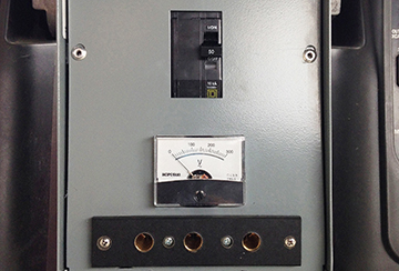
Paralleling Control Box front panel with 50A/240V Two Pole Breaker (top), Voltmeter (center), and optional 240V Bates receptacle (bottom.)
Step 4: Distributing Power
The 100A combined output of the paralleled generators is available from the 50A "Hollywood Style" 240V Twist-lock pigtail of the Paralleling Control Box (pictured below.)
50A "Hollywood Style" Twist-Lock Pig Tail Power Output.
Supplying 120V Loads
To provide power to 120V loads, such as small quartz lights, small HMIs, Kino Flos, or LED lights, requires that the combined 240V output be stepped-down to 120V by a 60-, 84-, or 100Amp Transformer/Distro. Which size Transformer/Distro you use will be determined by how large an HMI, or other 240V load, you plan to use as well.

Schematic of typical 120V distribution circuit
If you plan not to use a HMI, or other load that requires 240V power, then you would use the 100A Transformer/Distro to convert the combined 100A output of the paralleled generators to a single 100A/120V circuit.
If you plan to use a 2.5- 4kw HMI, or other 240V load that draws 20-30 Amps, then you would use the 84A Transformer/Distro to convert 84 of the combined 100A output of the paralleled generators to a single 84A/120V circuit,
If you plan to use a 6-9kw HMI, or other 240V load that draws 50-80 Amps, then you would use the 60A Transformer/Distro to convert 60 of the combined 100A output of the paralleled generators to a single 60A/120V circuit.
In other words, choose the Tranformer/Distro that will convert to 120V the balance remaining of the combined 100A output of the paralleled generators after powering your 240V loads.
Paralleling Siamese
To provide power to 240V loads, such as large quartz and HMI lights, requires a 240V Bates pocket. Depending on which is more convenient, the Bates pocket can be either hardwired into the Paralleling Box (as pictured above) or you can use a Hollywood Style Twist-lock Siamese (pictured below) at the Paralleling Box, at the step-down Transformer/Distro, or anywhere in the 50A/240V Twist-lock cable run to the step-down Transformer/Distro.
Which you choose depends on where in relation to the generator you plan to use a large HMI or other 240V load.
Distribution system consisting of 50' 50A/240V Twist-lock Extension, Paralleling Siamese with 100A/240V Bates pocket, and 84A Transformer/Distro
After running out the desired length of 240v Twist-lock Extension Cable and plugging in the Transformer/Distro and Paralleling Siamese (if powering 240V loads as well), energize your distribution system by setting the 50A two pole breaker on the Paralleling Control Box to the “On” Position.
Step 5: Load Sharing Trim
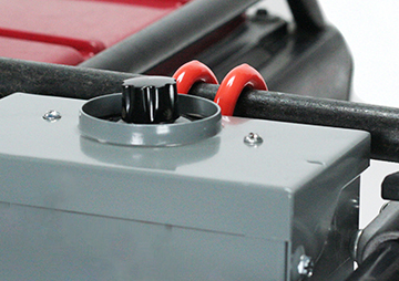
Load Sharing Control Knob
In order to optimize the combined output of two machines, the load must be split evenly amongst them otherwise one generator will reach its' maximum output while the other can still take more load. For this reason, our Paralleling Control Box enables you to adjust load sharing between the generators by simply turning a knob.
Trim Procedure:
First set the generator iMonitors to the VA setting. Next set the Load Sharing Trim Knob to the center position. Power a small
load on the paralleled generators. Now turn the Trim Knob towards the generator with the smaller VA until equal the load on
both generators is roughly equal.

If the generator on the right has picked up a smaller portion of the load than the generator on the left, simply turn the Load Sharing Trim Knob clockwise (as illustrated above.)

If the generator on the left has picked up a smaller portion of the load than the generator on the right, simply turn the Load Sharing Trim Knob counter-clockwise (as illustrated above.)

Once the load is shared equally between the generators (as illustrated above), apply the balance of your load and make a final adjustment to load sharing if necessary.
NOTE:
To share load equally between two EU6500s or EU7000s in parallel operation the generators must be trimmed to the exact same
voltage. Our Load Sharing Trim Knob accomplishes this by means of a variable resister that sheds the excess voltage as heat.

For this reason the parts of the Paralleling Control Box marked with the warning label above can get quite hot. Be cautious when handling the
Paralleling Control Box and allow it to cool down after use before packing it away.
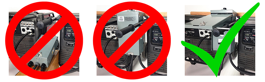
Do not obstruct ventilation of paralleling box by operating it on its' back (left) or with the lid closed (center.) Optimum ventilation is achieved by hanging
the paralleling box between the generators on a wooden closet dowel and propping the lid open with a metal rod as pictured above right.
Step 6: Shutting Down
To shut down follow this procedure: turn off your loads first. Then, turn off the 50A two pole breaker on the Paralleling Control Box. While the generators idle, wrap your lights and distro downstream of the Paralleling Control Box. After wrapping your lights and distro, then turn off each of the generators, disconnect the power leads from the Paralleling Control box to the generator, and only then disconnect the ground wires to the frames of the generators.
Extended Run Fuel Tank with Pump Cap (Optional Accessory.)
The Pump Cap replaces the OEM cap that comes with your generator only when you are using the generator in an extended run mode. DO NOT DISCARD YOUR OEM GENERATOR CAP. You will need the OEM cap to transport your generator to and from set and anytime you use your generator in a non-extended run mode. The Pump Cap is not designed to operate on your generator when it is not connected to the external fuel tank.
Operating Instructions:
1) Fill both the generator fuel tank and external fuel tank to capacity. Situate the external fuel tank and generator are on level and secure ground. This will avoid fuel leakage hazards.
2) Place external fuel tank on an apple box next to the generator such that THE EXTERNAL FUEL TANK IS NOT HIGHER THAN THE GENERATOR FUEL TANK (see picture above.)

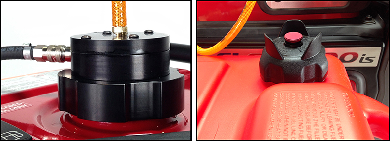
3) Remove the OEM cap and fuel strain basket from generator and insert the Pump Cap (see picture above. ) Do not fasten the pump cap at this time.
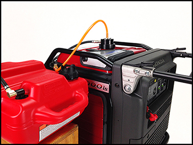
4) Connect the air hose that comes out of the Pump Cap to the air coupler on the top of the generator (see picture below.) Pull ring of air coupler forward to make sure it is locked securely.
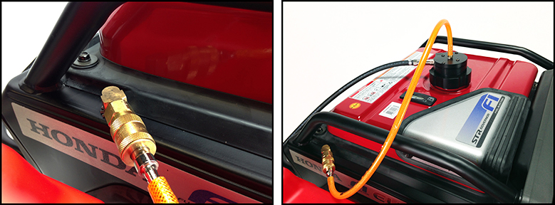
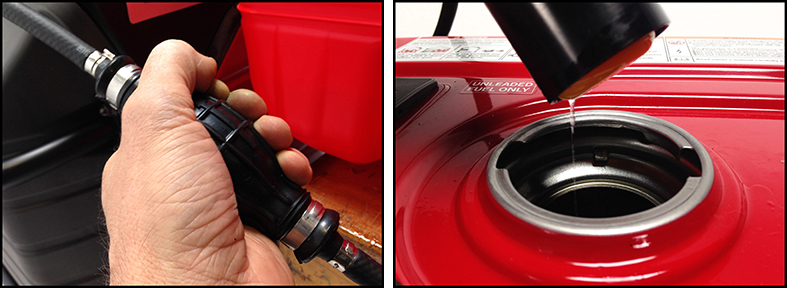
5) Attach the fuel line from the external fuel tank to the Pump Cap fuel coupler. Pull ring of fuel line coupler forward to make sure it is locked securely. Open the vent on the fuel tank by turning the red button on the external fuel tank cap counter clockwise (see picture below.)
6) Start Generator. Holding the Pump Cap above the tank opening of the generator in one hand, squeeze the primer bulb on the fuel line until fuel drizzles out of the Pump Cap (see picture below.) Stop squeezing the primer bulb. If the fuel continues to drizzle from the Pump Cap for 20 seconds after you have stopped squeezing the primer bulb the Pump Cap is operating.
7) Insert the Pump Cap into the generator fuel tank and give a slight turn. The Pump Cap should fit loosely but securely so that it cannot be removed
without twisting it back to its' original position. DO NOT OVER TIGHTEN PUMP CAP.
Note: To prevent fuel spills, the Pump Cap is designed to shut off automatically when the generator fuel tank is full, which means it will not
draw gas from the external fuel tank until the fuel level on the generator fuel tank has dropped.
8) After use, disconnect the air hose from the generator and the fuel hose from the Pump Cap. Remove Pump Cap
Note: the Pump Cap works by creating vacuum pressure and so there will be a small amount of fuel in the cap that may spill when it is removed.
9) Reattach fuel strain basket and OEM generator cap. Make sure the OEM generator cap is fastened securely before transporting the generator. Before transporting the external fuel tank, securely close the vent on the external fuel tank by turning the red button on the external fuel tank cap clockwise.
THE IMPORTANCE OF MAINTENANCE
Good maintenance is essential for safe, economical, and trouble-free operation of lighting loads. It will also help reduce air pollution. For these reasons follow the maintenance schedules contained in the generator’s operating manual.
Please let me know if you need any further information.
Guy Holt
ScreenLight & Grip
rentals@screenlightandgrip.com
Phone: 617-224-8534